by Wilber W. Caldwell
Foreword
Background
Overview
Analyzing the Space: Planning Overviews, Preliminary Lists, and Initial Sketches
Selecting a Scale
Developing a "Master Rough" Sketch
Developing Other Sketches from the "Master Rough" Sketch
Selecting the Brand of Track and Turnouts You Will Use
Working the Xtrack CAD
Creating a Schematic Track Plan Rendering
Designing a Yard
A Brief DCC Primer
Power Districts and Blocks
Block and Turnout Names, Addresses, and Labels
Bench Work Drawings and Plans
Wiring Planning, Drawings, Diagrams, and Schematics
Planning DCC Device Wiring
DCC Device Placement
Mounting DCC Devices
Planning LED Lighting Circuits
DC Power Supply Planning
Planning the Overall Flow of the Landscape and Tweaking Track Elevations
Bridge, Viaduct, Overpass/Underpass, and Culvert Planning
Mainline Signal Placement
Train Room Lighting Planning - Daylight
More Train Room Lighting Planning - Considering Alternatine Systems and Effects
Planning the Lighting of Layout Structures
More Detailed Topograghical Planning
Labels
Conclusion
Foreword
My current model railroad project, The Altamont and Blue Ridge 2, is my fourth model railroad. When I began thinking about this new layout, I started a blog called "Starting Over." My daily posts detailed my thoughts and my progress throughout the two-year planning process. It now occurs to me that, if I reorganize, edit, and append this material, I will have all the elements of a comprehensive model railroad planning tutorial. Please note: The A&BR2 is a N scale model, so the examples and specifications in this tutorial generally relate to my own work in N scale. However, if you are working in HO, all of the planning strategies detailed here will still apply if you simply substitute HO specs.
Background
I built my first serious layout after I got out of the Army in 1968. It was a 12' x 14', conventional, cab control HO scale affair featuring hand-laid track and very mountainous terrain. Although the track was completed and trains were running smoothly, the scenery on layout was never really finished because I moved to another house before I was done.
My second effort was begun in the early 1980s, when I constructed a second HO layout, and began to experiment with computer control. This layout occupied a 14' x 18' bedroom in my home and was pretty much finished by 1990. In those early days, before DCC, there was really nothing much available in the way of dedicated model railroad computer control software or hardware, but I was able to fashion a workable computer control setup using software I wrote myself in Basic and lots of relays, resistors, and voltage sensors, all hooked up to an early PC via a parallel I/O board. By today's standards it was pretty crude, but it worked after a fashion.
 |
Sadly this faded image is the only photo I have of my l980s HO layout |
In 2008, I began work on the Altamont and Blue Ridge 1 in a custom built 21' x 12' garage-bay train room with wrap-around backdrop walls, custom lighting, and a dedicated HVAC system. The AB&R1 featured complete DCC control employing primarily Digitrax components and Freiwald "TrainController" software running on a PC. This was my first N Scale effort, and it was pretty much complete by the end of 2015.
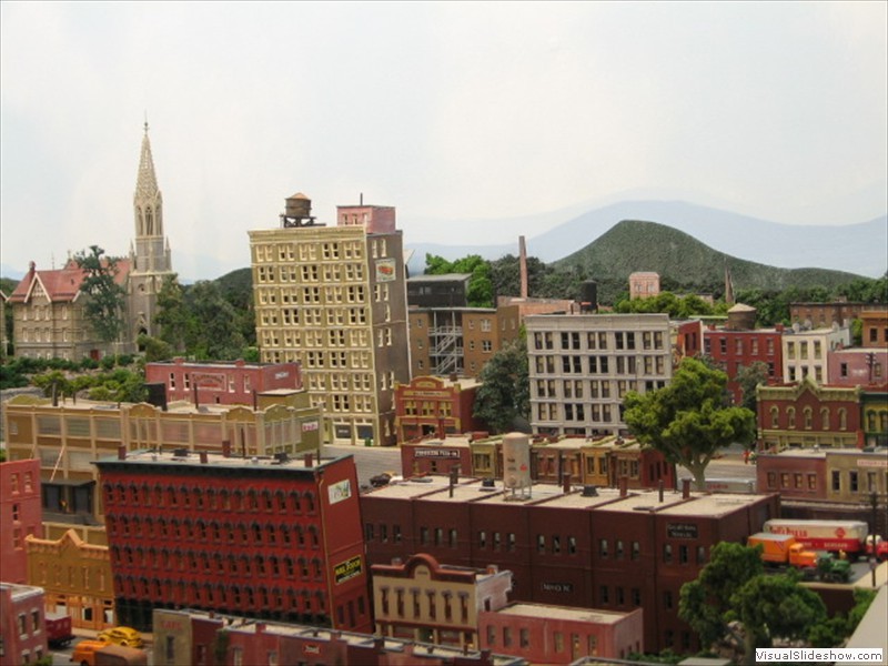 A&BR1 - City of Altamont |
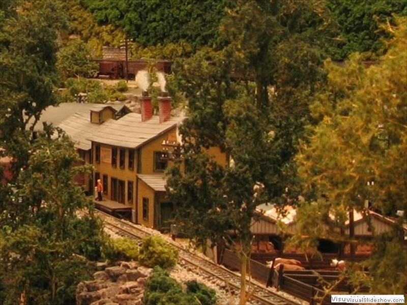 A&BR1 - Stock Yards at East River |
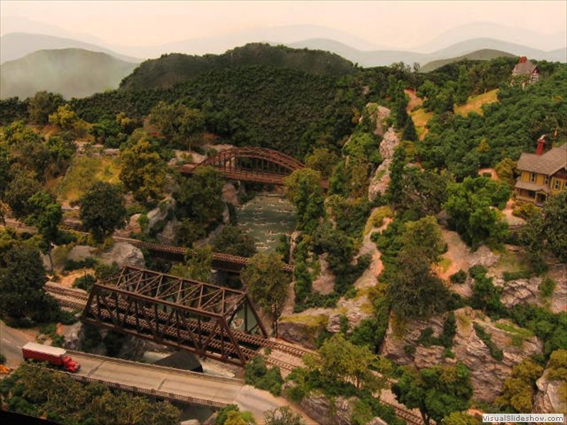 A&BR1 - East River Crossing |
 A&BR1 - Westridge |
Overview
Like every experienced model railroader, over my almost 50 years of modeling, I have developed various techniques that work for me. There is nothing magical about the way I do it. Still, I would like to share my methods not so much to suggest how your should build your model railroad, but rather to detail a planning chronology that considers all of the elements, drawings, schematics, and design concepts in the model railroad planning process using my own plans and methods as examples.
Analyzing the Space: Planning Overviews, Preliminary Lists, and Initial Sketches
Clearly the first step in planning a model railroad is to carefully consider all of the possibilities and challenges inherent in space available for its construction. Thoughtful analysis of the space to be used will inform virtually every aspect of the planning process: scale to be used, bench work structure and configuration, track planning, scenery, lighting, HVAC, electrical ... everything. The decisions you make at this early stage are the most important decisions you will make, so take some time here. I have spent over two years planning the A&BR2, and the first year of this was spent determining how to best configure and use the space available.
This first overview planning is quite complex because so many of the elements you must consider are interactive. That is to say, a decision regarding the bench configuration will effect decisions regarding scale and track plan and scenery and lighting etc. and vis a versa. In this regard, I strongly suggest that you read all the way through this entire tutorial before taking this first step. As you read, make some notes. Make lists of questions to be answered, alternatives to be considered, possibilities with pros and cons, potential problems. Also keep a list of the things you want to include in your model railroad along with all specifications to be observed. If you have had other layouts before, it is a good idea to make a list of all the things you would change if you had it to do over again. Also make a list of things that you like and would not change.
These lists should get into every aspect of model railroading. Do you want DCC? How will you handle sound? What area on the country are you modeling? What road names will service this area? Will you have a yard, a turntable? How many towns will there be, how many depots, rivers, and so on? Where will there be mountains? Will you have grades, and how steep will they be? What is your minimum turn radius? What brand of track and turnouts will you use? What kind of switch machines will you use - what brand of DCC booster and peripherals? How will you hide that ugly air conditioner duct in the middle of the room? How will the bench be constructed. How will you service track in the tunnels and access any hidden track? Will there be double track mainlines anywhere? And on and on. At this point, a careful read-through or two of this entire tutorial will help you develop your lists and questions and define problem areas.
The next move is to begin to do rough sketches of the bench work overlaid with very rough visions of mainline track plans. As you do these sketches, keep in mind some fundamental guidelines. For example, in N scale, the minimum radius is said to be 18 inches, but I would never build a turn that tight. Generally it is best to try to keep turn radii as large a possible, no less than, say, 25 inches in N. Remember, even a 50 inch turn radius in N scale is far tighter than what one would find on the prototype. On the A&BR2, I try to hold to 30 inch minimum radii, although I do have a couple that are more like 28 inches. Likewise, I recommend that no grade exceed 2 percent, and for N, I would use center to center mainline track spacing of 1 1/4 or 1 3/8 and maybe 1 1/2 inches on curves, and
1 3/4 inch overhead clearances on tunnel portals and overpasses. There is a lot written on line about these kind of specs for both HO and N scales. You will find a divergence of opinion in some areas, so inform yourself before you begin, and make you own choices in order to develop your own list of specifications for you railroad. Then, do lots of sketchs! Explore the possibilities of your space. Get ideas from books and on line. If you have not selected a scale, you will have to do a different set of sketches for each scale. Your rough sketches will inform your selection of the best scale.
Selecting a Scale
The question of scale is paramount. Which scale should you choose? There has been a great deal written on this subject, and generally both camps remain entrenched. Both scales have advantages and disadvantages, and there are a number of areas to compare.
HO just feels good, and operationally it seems to me a bit more robust and stable in almost all regards. Track work, loco mechanics, wheels, trucks, and couplers are all less delicate, easier to work on, more sturdy, and a bit more forgiving. Still, under ideal circumstances, today's N scale models can be set up to run quite reliably. However, as we all know, circumstances are not always ideal, and it takes perfect track work and constant, jeweler-like precision to keep a large N Scale operation perfectly tweaked and operating without incident. For me, its more durability and stable mechanical performance is the largest asset in HO's time-honored bank.
Another point in HO's favor is the way it behaves with DCC computer control. HO locomotives can be calibrated more precisely than N units, and this calibration will remain more stable in HO units. This is not a decoder or a software issue. N scale decodes are excellent, and most control software is essentially the same for both scales. The difference in performance is a function of the size and mechanics of the locos themselves and the stability of the ballistics of their motors. As we all know, speed calibrations are not absolute and they can change with temperature, lubrication, wear, and other friction issues. N scale models are simply much more sensitive to such changes, and, although they can be tweaked to stop within a few inches of a measured distance into a block, their stopping accuracy will probably slide with time and changes in circumstance more than HO models do. A perfectly calibrated HO model might consistently stop within an inch or so of a designated point and, all things being equal, it might hit that mark for months and months. Overtime, N scale models will probably remain pretty close, but they will be more likely to slide off the mark betweeen lubrication and cleaning intervals or as other things subtly change. Still in most cases, they remain close enough for me.
If you are are married to sound decoders and in-train sound chips and speakers, then, of course, HO is the clear choice. The modern N scale sound decoders are fine, but the on-board space limitations in N scale still present problems in my opinion. If I go with N scale, I'll continue to use Freiwald Software's TrainController and the associated Freiwald 4D surround sound. It may not be quite as versatile or believable as the decoder sound, but, when set up and tweaked properly, it is pretty impressive. For me, it's the only way to go for sound in N scale.
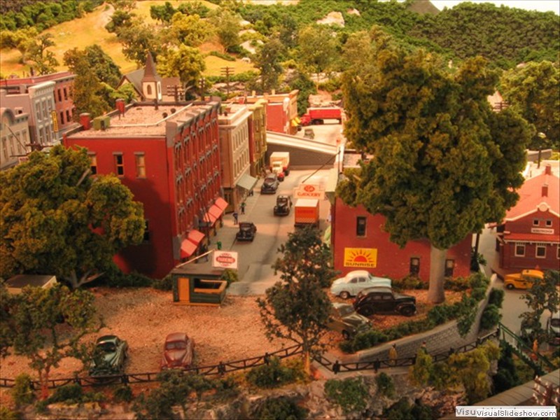
On the visual side, when modeling in HO, one needs a great deal of space to achieve any kind of over-all panoramic realism. Because of its size, individual "scenes" in HO can be much more detailed, however only a gargantuan train room allows enough space to get these 3 dimensional compositions far enough apart to achieve anything believable in overview. In HO, in the average, largish train room (say, 20' x 12'), one tends to create crowded, pressed-together strings of perfect little vignettes, which, although individually realistic in close-up, somehow fail when viewed as whole. With such a forced compression of scenes, almost all but the largest HO layouts fail to achieve a consistent, realistic, natural flow of the over-all landscape. What is more, if one limits the against-the-wall bench work to, say, 36 inches, as I do, in HO it becomes more difficult to create the kind of false perspective needed to effectively hide the marriage of the backdrop to the bench top.
All of the above-discussed visual issues pretty much disappear in N scale. In fact for me, modeling in N has a completely different focus than modeling in HO. In HO, one tends to focus on individual scenes, whereas in N, one's principle focus tends to be the panoramic sweep of the landscape as a whole. None of this should be construed to imply that one can't create detailed scenes in N. As this web site I hope proves, one certainly can do detailed work in N, while at the same time, the diminutive size of N scale structures, trees, vehicles, figures etc. tends to discourage the kind of "rivet-counting" analism one sometimes encounters in larger scale modeling. In my mind, the ability to create convincing natural, sweeping, panoramic landscapes containing entire towns, large yards, and sprawling industrial developments, coupled with the ability to create the illusion of receding distances near the backdrop make up by far the largest deposit in the N scale account. In fact, for me this is the game-breaker in N's favor.
|
A 34 inch deep section of the current A&RB1 modeling a mountain river crossing. Notice in N Scale there is ample room for a roadway, a double track crossing behind, along side a single track crossing, and a distant "high line" crossing. Notice the forced perspective achieved by using progressively smaller trees beyond the high line track to the left and the z scale house on the hilltop in the upper right hand corner of the photo. Achieving this kind of panoramic result in a front-to-back space of only 34 inches would be difficult if not impossible in HO. |
To be sure the cost should be considered. At first blush, N scale would appear quite a bit less expensive. The cost of N scale structures, track, turnouts, and locomotives can be as little as half that of corresponding HO products. But remember, working in N, you will have four times the in-scale space to fill with track, structures and locos. So the cost issue is something of a wash. In my case, a large point in N's favor is the fact that I already have 50+ turnouts, 15 Southern Railway and L&N locomotives, 80+ units of rolling stock, 150+ fully detailed structures and so on. I suppose I could sell this stuff, but I doubt I could get anything near 50 cents on the dollar for it. So, this too sways me in the direction of staying with N scale. Frankly, I am really looking forward to building the train room and bench work, laying the track, wiring, and creating the landscape. I am not looking forward the assembling, painting, weathering, and detailing 80 new box cars, and 150 new structures.
Not too many years ago, one of the main arguments against N was the notion that there was just not as much stuff available for N scale as there was for HO - not as many loco types and models and road names, not a full array of structures, not enough other toys and whistles and bells, so to speak. As we all know, those days are long-gone. N scale catalogs overflow with choices, and a number of decoder manufacturers scramble to create full function, easy-to-install, drop-in boards for myriad of loco types. Perhaps N still suffers from standardization issues between Europe and the US, and problems that arise from lack of interchangeability among several different axle lengths and wheel sizes, track codes etc., but these issues are addressable. Indeed, N scale has come of age, and it may very well represent the future of the hobby.
A&BR2 will be N scale, so most of the rest of this tutorial will be oriented to that scale. Nonetheless, those who plan to work in HO scale or even O scale can still fully benefit from this tutorial. You will simply have to substitute HO specifications and dimensions. This should not present a problem. In fact I recommend that those who have selected to work in N scale go on line and read all they can about N specifications for track spacing, overhead clearance, turn radii, grade steepness etc... everything. As I said in the beginning, there is nothing magical about the way I do it. There are indeed parameters within which you need to work in any scale, but you may as well select from within these the exact specifications that seem right to you and the one that best fit your space.
Developing a "Master Rough" Sketch
With each new rough plan, get out your lists of wanta-haves and questions and specifications and potential problems and see how each plan holds up to an item by item scrutiny. Do not get in hurry. After you develops a few plans your like, put them aside for a week or so. Think about it. Then revisit them with a critical eye. In the end you will come up with a scale and a plan that works for you and probably a short list of problems or challenges associated with that plan. No plan is prefect. There is always give and take. Remember, choosing the best plan is a matter of both gut feel and careful analysis.
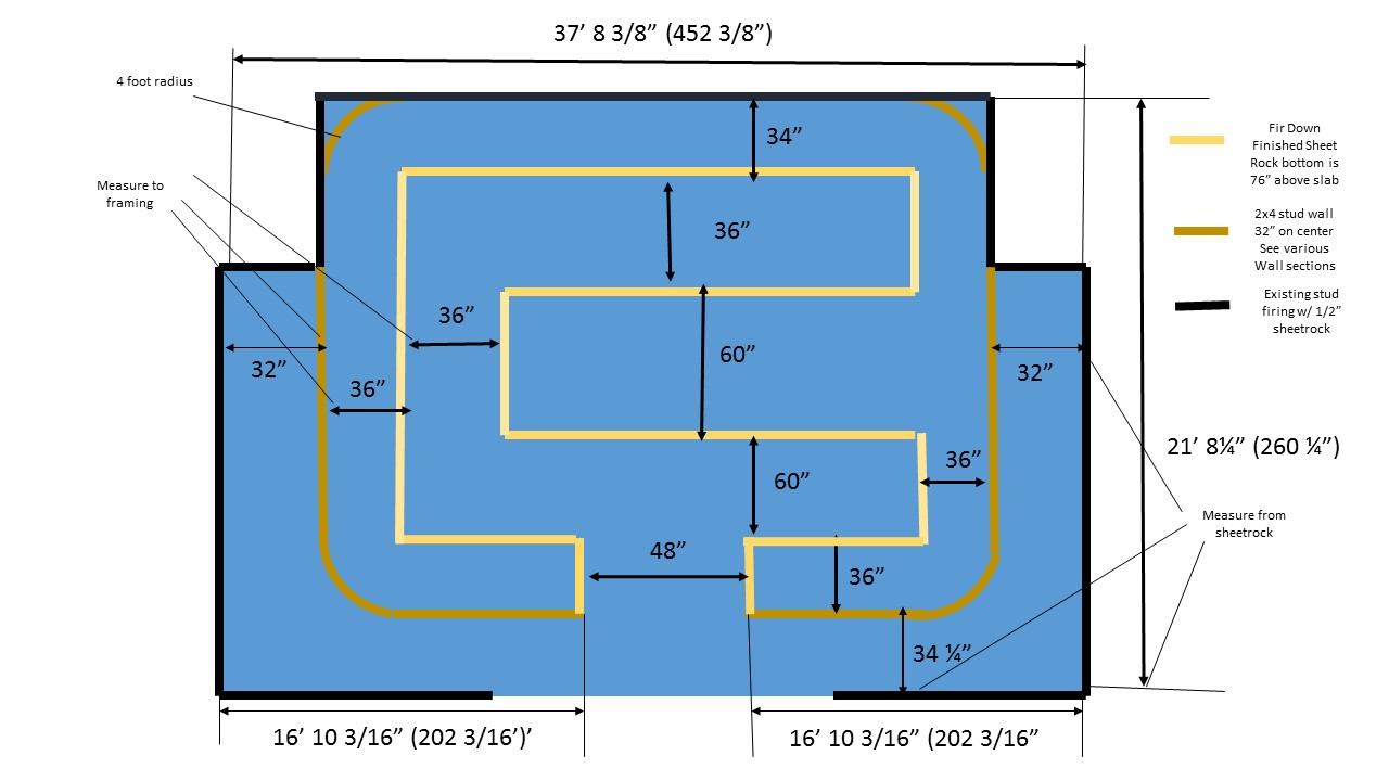
In the case of the A&BR2, I began my sketches with a simple footprint/floor plan of the new train room (Figure 1), and then superimposed various backdrop (Figure 2) and bench designs and different track plans (Figures 3 & 4). My wish list included 30" minimum radii, 2% maximum grades, 4 foot backdrop corner radii, and 36 inch-wide viewing aisles. In addition, I wanted to include a 36 inch-wide access aisle behind the backdrop wall from which I could easily access not only the under-the-bench area but also the space inside all the tunnels.
Figure 1 - 22 x 39
footprint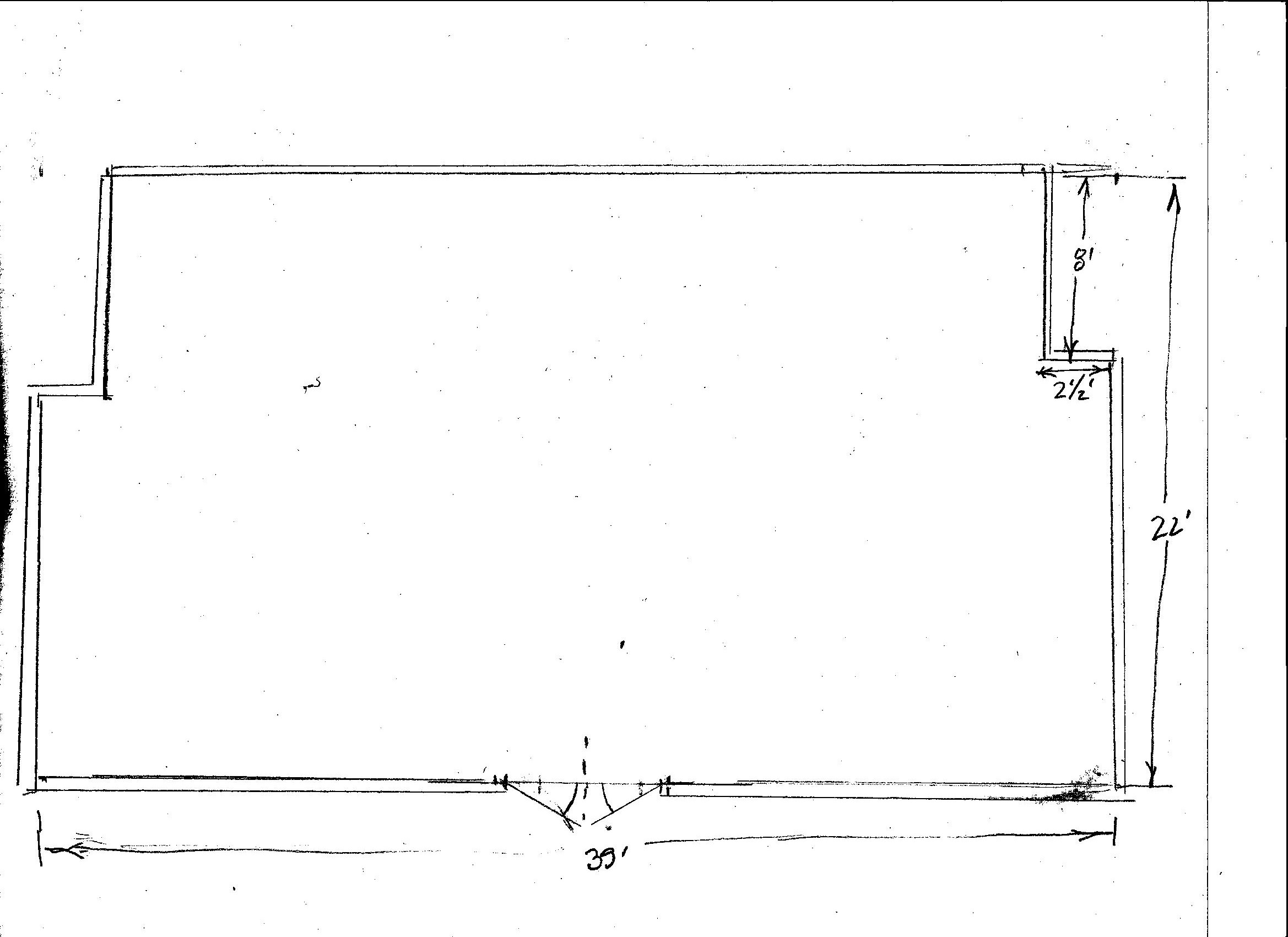 |
Figure 2 Backdrop walls
corner radii and
access aisles - 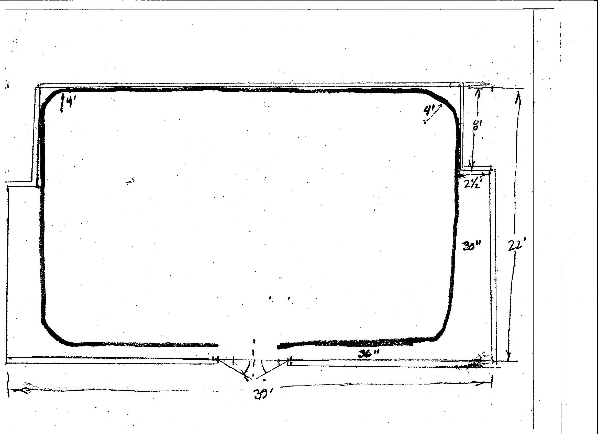 |
The room footprint readily lent itself to an aisle around three sides of the the room and to behind-the-backdrop access to tunnels in all 4 corners of the room, and once I defined the space I had to work within, I made a few bench work sketches, and finally I settled in on what appeared to be the optimal design. It was a bit of a compromise to not have all-the-way-around access aisles, but the 3 benchs, the 2 viewing aisles, and the opposing access aisle took the entire 22 feet of room width, and I wanted at least 32" of bench width (ideally 36") and 36" wide viewing isles. I've made smaller aisles on a previous layout and it proved to be a big mistake. So I gave up on the forth-side access aisle in favor of optimal bench and viewing aisle widths. Another slight compromise was the 5 foot wide turn-around sections and long center section - another six inches would have allowed for all curves to have a 30 inch minimum turn radii, but the space was just not there, so I settled for a near 30 inch radius for the outer mainline tracks and a 28 1/2 inch radius for the inner mainline track on the turn-rounds in the 5 foot wide sections. Then I began to sketch in a various mainline track plans, including the location of all yards, depots, and towns as well a rough idea of mountains and tunnels.
Figure 3 - Bench
work and viewing aisles 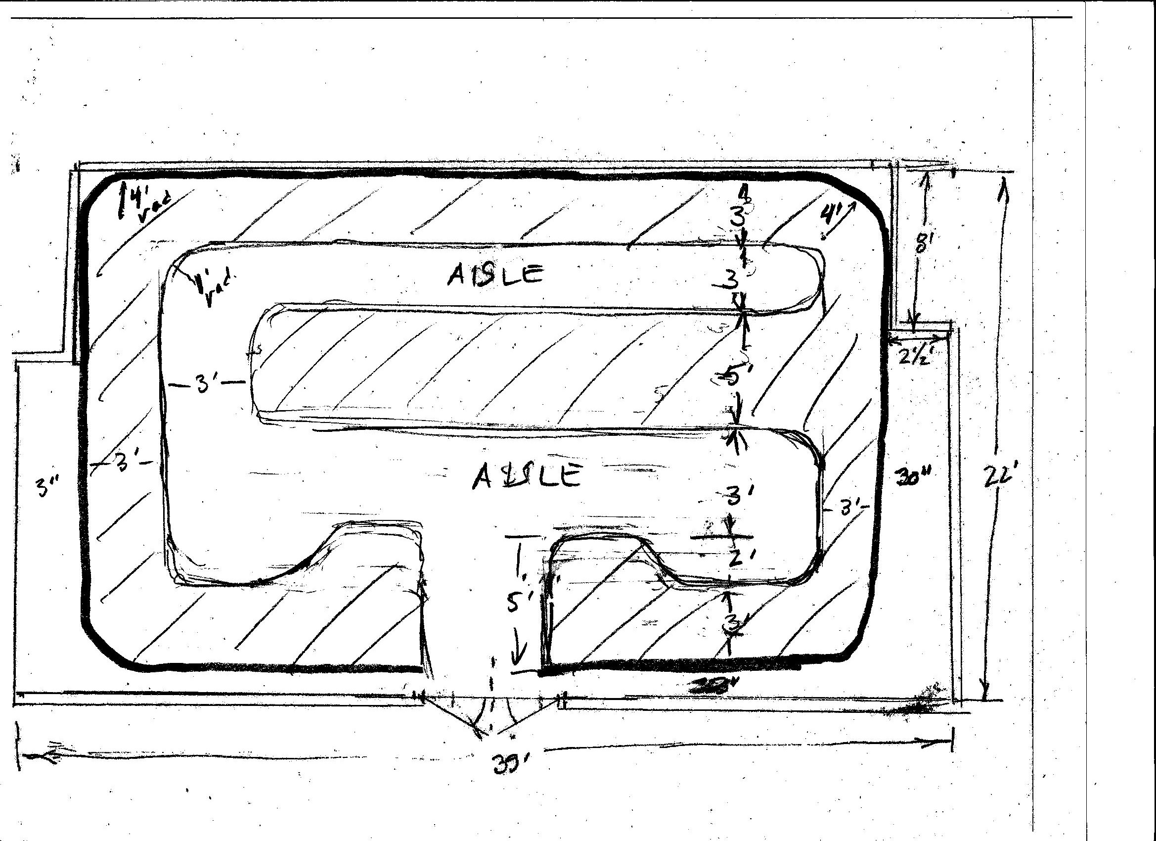 |
Figure 4 - Double track
mainline with reversing sections ("REV"), depots,
towns, mountains
(shaded) tunnels (dotted line), in-slab conduit etc. 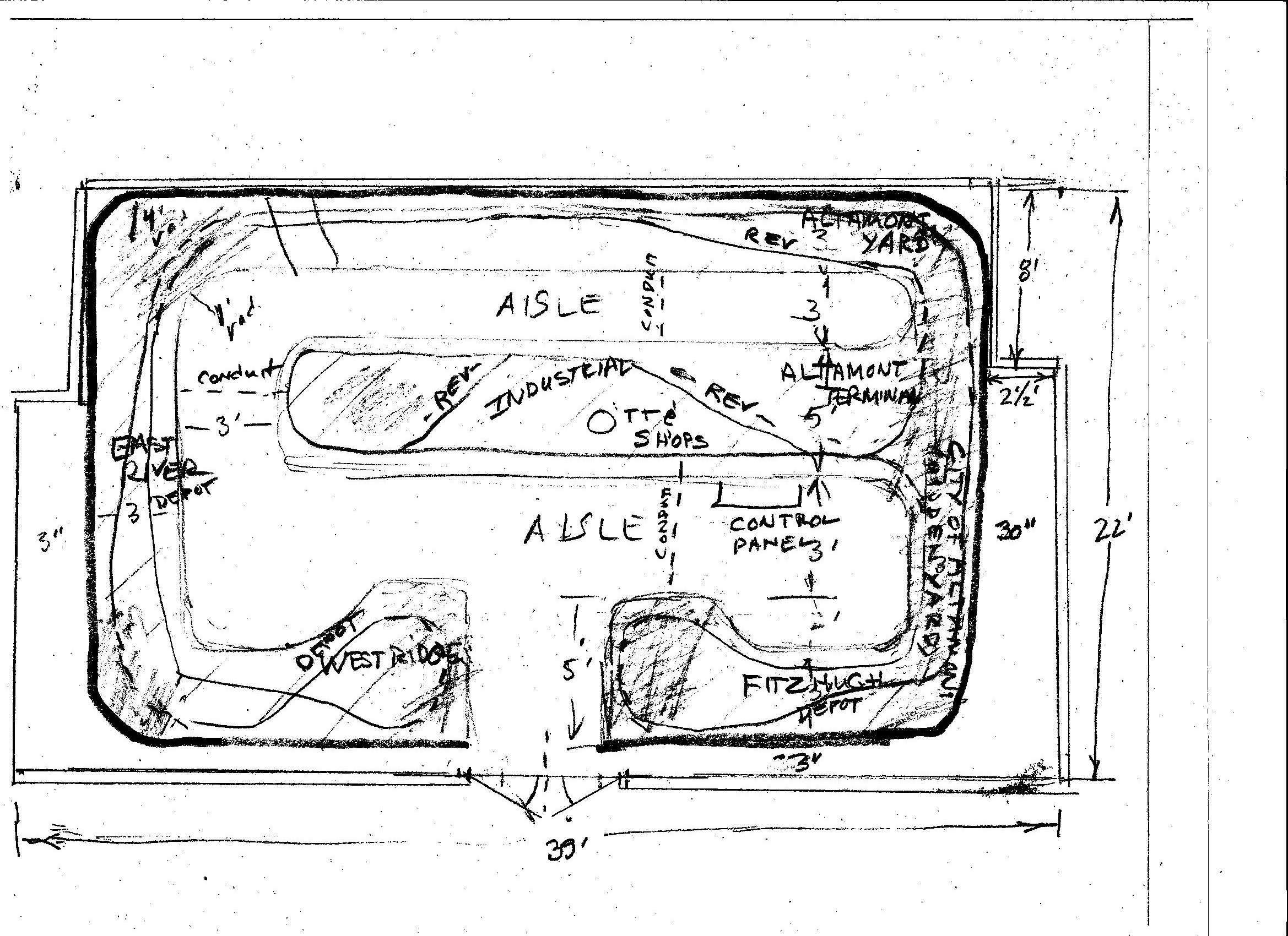 |
This looks really sloppy and rough, I know, but at this stage it what is needed. Here we are dealing with rough ideas, considering options, maximizing possibilities. This is brainstorming - dreaming - boundless, formless, thought.
Developing Other Sketches from the "Master Rough" Sketch
Once you hit on a rough plan that works in every aspect within your space and promises to include all your dreams, you have your "Master Rough" sketch. Before you move on to the next step where things will get much more orderly and precise, you should make other sketches using this "master rough" as a template. Referring to the appropriate sections of this tutorial that follow, make sketches of room lighting, your AC outlet layout, the location and design of the control panel and of all DCC devices with careful considerations regarding wire gauges and lengths. Rough sketches of backdrop wall sections and bench work construction are also a must at this stage. Also you should now sketch out designs and track plans for your yards and sidings not shown on your "rough master" sketch adding necessary crossovers on the mainlines as you go. Finally, spend some time working on a rough elevation plan that includes grade percentages and the location and type of all bridges and overpasses. Again, refer to the appropriate subsequent sections of this tutorial to aid you in making these initial rough sketches. The general idea here is to evaluate and modify your "master rough" plan as you consider all aspects of the project, and to begin to document each aspect with a rough plan of its own. As I said before, all of these different elements are interactive, so it is best to first consider each element individually and then as part of the whole.
An example of this kind of comprehensive rough planning on the A&BR2 is the under-the-slab conduit that I added very early in the construction phase. After I had developed my "rough master" track plan, I calculated that, with my new bench configuration in a train room this size, some of the wire runs from the DCC block occupancy sensors to certain distant sections of the track would be a bit longer than recommended cable length maximums, that is, if I had to run then all the way around under the bench to the other side of the room from the central control panel. So I added three 3 inch conduits to enable me to run wires under the viewing aisles from the control panel attached to the long center section directly to the other three sides of the room that are not connected to the center section.
Another example concerns room lighting. I wanted to switch all room lights at the control panel, but I faced the problem of needing at least a little light to get to the panel when first I first entered the darkened room. At first, I considered a single entry light fixture above the panel that could be switched at the door and at the panel. Then I realized that, since the HUE lights that I use for colored light effects like sunrises etc. are controlled by WIFI and thus would always be switched and controlled by the computer, I did not need to switch them at the panel. So, since they always come up set to a nice natural white light after being powered off at the switch, I called for them to be switched at the door. This would allow me plenty of light upon entering the train room and the ability to turn them off upon exiting.
After you have sketched your final "rough master" plan and sketched out how all of the elements on your layout will work within this plan, it is a good idea to skim through this tutorial yet again with an eye specifically to your new plan. As you go, again, amend your rough sketches and lists of features, problems, questions as you evaluate each section with an eye to your emerging overall plan.
Once you are satisfied that you have designed and sketched out a plan that works with everything and that none of the problems associated with this plan are unsurmountable, you can move to the next steps in which you will develop a detailed, very precise track plan, as well as all the detailed working drawings, wiring schematics, block and turnout lists and labels that you will need to begin the construction of you new layout.
Selecting the Brand of Track and Turnouts You Will Use
I use a CAD program to create final track plans, bench work working drawings, room lighting schemes, some of the overview wiring diagrams, and much more. The program I use is called Xtrack CAD, a freeware product that is discussed in detail in the next section. Before you begin with Xtrack CAD, it is a good idea to select the brand of track and turnouts you plan to use, because XtrackCAD can insert very accurate track and turnout components into the rendering of your plan using specific libraries of the components available from all the major manufactures. In any scale, a turnout is not just a turn out. Each manufacturer makes different lines that vary slightly when it comes to exact dimensions, sleeper spacing, angle of throw etc. Using the libraries associated with Xtrack CAD to insert precisely calibrated component renderings into your track plan drawing will save an enormous amount of time and realize a level of accuracy you could never achieve manually. Accordingly, it is necessary to select which brand of track and turnouts you plan to use before you begin to draw in Xtrack CAD.
There is wealth of information regarding track selection on the Internet, and you should read up on the pros and cons of each of the various standardized codes and the different brand name offerings. Go to a hobby shop and/or get a catalog and look at the alternatives. Then check out some on line forums to read user feed back and discussion. This is not rocket science, and all of the brands are pretty good. Only you can decide which is best for you. The following paragraphs will describe my N scale selection process, but you can make the same considerations if you are working in HO or O.
My original plan was to use Peco Code 55 flex track and turnouts on the A&BR2. I have had a good experience with Peco on the A&BR1 and continuing to use it on the A&BR2 would have allowed me to reuse all the track and turnouts from the A&BR1. This could have saved me some money if I had stayed with Peco. But I spent some time looking into the possibility of switching to Atlas Code 55, which not only looked much better to me, but is also slightly less expensive. In addition, Atlas offered a #10 mainline turnout, which appeared to me to be much more realistic that the largest Peco turnout, which is a #7.
The Atlas Code 55 track was more delicate, and it looked much better than the Peco product. The rub with Atlas was that I might have had to re-gauge the wheels on some of my locos and replace a lot of "cookie cutter" MicroTrains wheel sets with Atlas-friendly alternatives. I ordered 5 lengths of Atlas flex track and 2 turnouts, in order to run some tests and see how it looked, felt, and how my locos and rolling stock performed on it.
I reasoned that switching to Atlas and buying all new track wound mean that I could keep the A&BR1 up and running at least until I had the bench work completed and all of the track laid and wired (without all of the Tortoise Switch Machines installed) on the A&BR2. It would also allow me to build, on the work bench, prefabricated modules with track laid and switch machines and signals installed and wired while I waited for the train room construction to be completed. All I had to do is buy a new Digitrax DCS100, a universal panel, and a throttle: total = ~$275. On a layout this size, I was going to need 2 universal panels and 2 throttles anyway, and I probably needed a spare booster as well. I already had a spare BDL168 I could use for testing as I laid track on the A&BR2.
When the Atlas Code 55 flex track and the #7 turnout I ordered arrived, my first reaction was that they looked GREAT! A significant visual improvement over the Peco product - much more delicate compared to the Peco turnouts! After testing a number of my locos, I found that they all seemed to run well, and would probably not require much if anything in the way of wheel re-guaging. I would however have to replace a lot of MicroTrains "cookie cutter" wheels, but that was no big problem. Based on these tests and on the fact that switching to Atlas, allowed me to keep the old A&BR1 up and running until I was finished laying track of the A&BR2, I decided to switch to the Atlas track.
Before I ordered all the track and turnouts, I ordered 3 more Atlas turnouts, 1 more #7 and 2 #10s, so I had one each of the turnouts I needed for the A&BR2. I then painted and weathered these to see how that would go, and made my templates for the actual laying out of the track. I then ordered 10,000 inches of Atlas code 55 flex track and 86 turnouts (61 #10s and 25 #7s.) about $2100 - but I calculated that this only amounted to $850 more than if I had reused my Peco track and turnouts.
Working the Xtrack CAD
Xtrack CAD is a remarkable program, and its free. It takes a little time the get fully facile with it, but once you get the hang of it, it is a truly invaluable planning tool.
First of all, you can create absolutely perfect track work when using flex track, and it is accurate down to the tiniest fraction of an inch. Among other things you can, insert accurately drawn turnouts and structures from libraries of turnouts and structures featuring all the popular brands, monitor all radii and grades to insure you have not gone above or below your set maximums and minimums, create perfect track alignment and spacing, and automatically calculate and insert easements and curves. If you use the automatic track joining feature, the program will not let you join two sections until the positioning of the sections to be joined is exactly correct, and then it will insert all the segments needed to join your sections, including any curves and easements, while allowing you to control the size and sweep of any radius to be inserted. It takes a little getting used to, but once you master the track-creation features, it is incredible. You can view the complete track plan in overview, or zoom into any section you like until you get a accurate-down-to-the-individual-tie closeup view. You can also label all components and sections, and custom color-code various components and drawing elements.
While creating my track plan for the A&BR2 , I used Xtrack CAD to monitor grades percentages and turn radii. I set the desired overall minimum radius to 30 inches and maximum grade to 2%, then when I begin creating the plan, the program warned me if I created anything that does not conform to these limits. With regard to the minimum radius, this checking takes place automatically, and any offending section of track will appear in red. With regard to maximum grades, in order to have the program check grades, I had to manually enter elevations at key points on the layout. Once a length of track was marked with an elevation at the ends of the two outer-most sections, the program assumed a uniform incline and computed the grade percentage. Again non-conforming sections appeared in red.
I did have to tweak my standards just slightly, reducing the minimum radius to 26" and the maximum grade to 2.1%. This did not represent a significant compromise, and only three curves are under 30 inches. Most are well over that. Likewise only one grade exceeds 2% and that just barely.
XtrackCAD also allowed me to set the spacing between parallel tracks. I used 1.25 inches from center line to center line on both mainlines and in yards, with a slightly wider spacing for double track radii in the corners or in the turnarounds.
When I begin to build, I'll use detailed Xtrack CAD renderings guide me in the actual track laying process. Some modelers printout 1 to 1 full scale pages and paste them to the homasote and lay track right over the top them. For me, a large scale print out (say 6 to 1 or so) with the grid set to 1 inch allows me to locate track on the homasote surface with very precise accuracy. The print layout routine in Xtrack CAD is a bit difficult to master, but again once you get the hang of it, it too is great.
In addition, XtrackCAD can be used in the planning stage to create a great deal more than just your track plan. The program features pretty good drawing tools with multiple colors and multiple layers that can be turned on to view or off to hide all sorts of other planning drawings. I like to dedicate a layer to the room configuration. I also use Xtrack CAD for drawing a layer detailing the walls and bench work construction over which I will create my detailed track plan. In conjunction with the track plan, I dedicate a layer to signal placement, one to the placement of all DCC devises like stationary decoders, and power managers, and occupancy sensors etc. and one to all labels like block names, turnout names, etc. Additionally I have a layer that shows the AC electrical scheme of outlets, and one for the overhead room lighting, as well as several layers dedicated to layout wiring.
So I use Xtrack CAD to create and display a single master plan for the entire model railroad: all to perfect scale, all color coded, and all viewable in any number of different combinations of elements. A few examples appear below.
Walls and Bench Work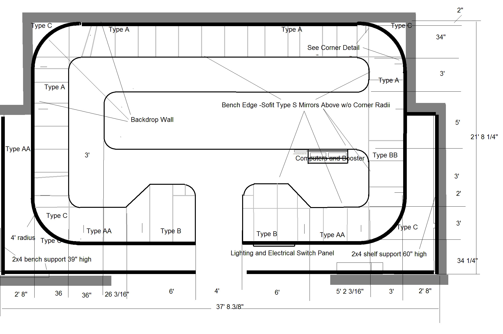 |
Electrical and Lighting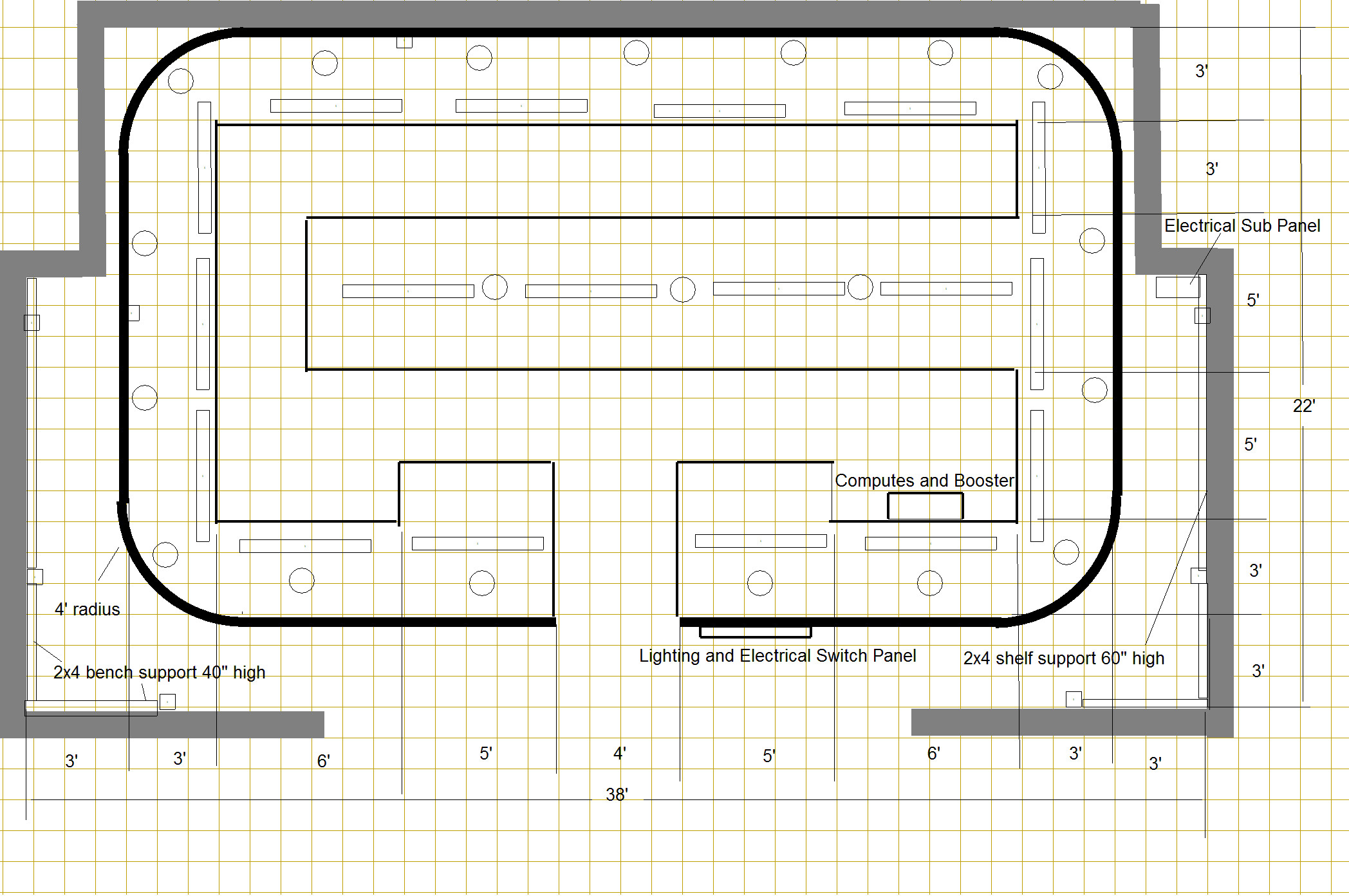 |
Track Plan with Topo and
Roads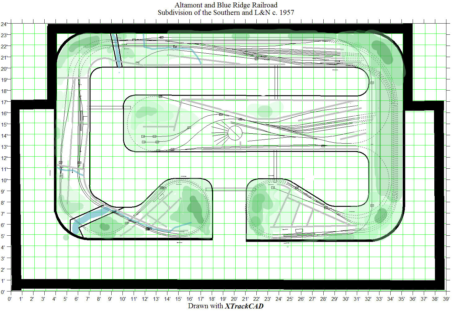 |
Track Plan with Wiring
Overview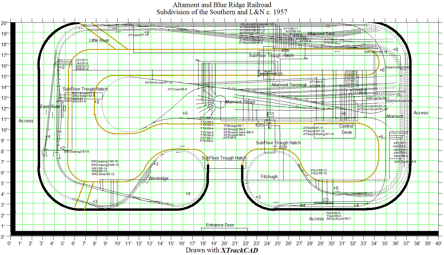 |
Medium Zoom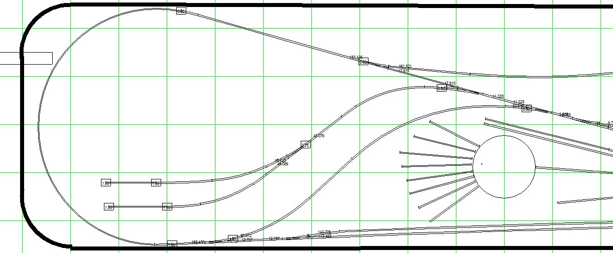 |
Medium Close Up with
my Handwritten Track Placement Notes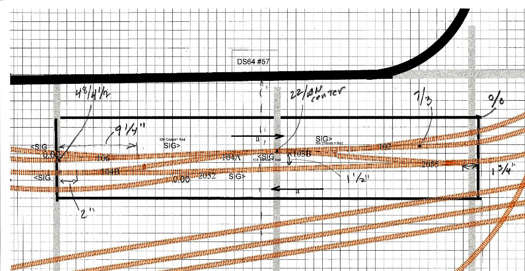 |
Once you have worked through this entire tutorial, and you have all of your layers in XtrackCAD completed, you can begin to evaluate your plans in detail. Undoubtedly, you will make changes as you work to layout everything in XtrackCAD, and there will be many more changes to come once you have an exact design rendered, diagrammed, and documented. With your completed XtrackCAD renderings and your other diagrams, schematics and lists you can examine your scheme for any number of points of view: traffic flow and operations, elevations and topography, clearances for structures and roads, crossings, bridges and under/over passes etc. The final tweaking process on a largish layout takes months and you will be constantly updating your Xtrack CAD rendering.
Another very cool feature of XtrackCAD is that it keeps a running inventory of all the track components used in your track plan, so when you are done with the design and are ready to order track and turnouts, you will know exactly what is required.
Creating a Schematic Track Plan Rendering
As great as Xtrack CAD is, it does have its short comings. One of them is this: because it is so accurate and detailed, in overview it is often much too complex to allow a clear and easy-to-evaluate picture of traffic flow and operations. To easily evaluate operations and traffic flow on your new layout, you need a simpler more stylized track layout rendering. You could use your :Master Rough" sketch for this, but you will probably need something more complete and much neater. The TrainController switchboard is ideal for this. It is simple in overview and yet very detailed, including every label, turnout and signal. If you are going to use TrainController, you are going to have to create it later anyway, so you may as well create it now and use it for evaluating traffic flow. If you do not plan to use TrainController, you can create your own stylized rendering by hand in order to assess how traffic will move on your proposed track plan; or you can download TrainController for free and use it in the demo mode to 30 days. It will only count the days on which you make changes, and once your 30 days are up, it will not erase your renderings, it will simply not allow further changes or real time operations until you purchase the software. So if you draw your layout in a day or so, and if you are careful as to how often you enter your changes, you can effectively use this relatively expensive program for your planning for free.
This is not a TrainController tutorial. TrainController is a complex piece of software, and it takes years to master even for computer experts. Still, the switchboard drawing potion of the program is quite straightforward, and I recommend you use it in your planning. Below is the switchboard for the A&BR2. Notice that the stylized, not-to-scale nature of this rendering makes it much easier to assess the way the track plan works and where the signals should be placed.
 |
A tool like the stylized schematic switchboard above is invaluable in evaluating traffic flow and signal placement and also in the signal programming that will come later. How does a train get from point A to point B, does it have to travel for any distance over a mainline in the wrong direction? Is another crossover needed? Exactly where are your detected block, and where are your undetected routes? Where should mainline signals be placed and exactly which blocks and turnouts will each signal monitor? This is the kind to questioning that needs to go on, and a simple more stylized schematic is a big help in this process. There will be many tweaks to be made. Just to get you thinking as you move forward, here is a partial list of the changes I made to A&BR2 track plan between the time a first drew the track plan in XtrackCAD and in TrainController and the time I began to lay track. I include this list to illustrate that your are far from finished with your track plan, and that you need to allow time for and keep an open mind to making changes. Don't get hung up here. The thinking behind all of these changes will be explained in detail later in this tutorial.
1. The first change I made regarding the new design followed a simple maxim: "Try to avoid running too much track parallel to the edge of the bench work." If all of the track is parallel to the edge of the narrow benches, one quickly gets the feeling that the layout was designed to conform to the bench, and the result is therefore somewhat artificial looking. Accordingly, I altered the original plan to set the ladder at Altamont Terminal and the highroad track at East River at angles to the edge of the bench. I have also created a sweeping curve in the ladder at Altamont Yard to break it away from the predictability of paralleling the bench edge. It doesn't take much, but all this will really help in the end.
2. The depots at East River and Westridge have sidings, and so I added cross-overs to accommodate trains approaching and departing on the mainline track away from the sidings.
3. I added a crossover near Little River to allow the EB highline to access the Altamont City line.
4.
I added a streetcar
line down the center of the main street in Altamont.
6.
7.
An architectural change
in train room size precipitated numerous changes to the track plan.
Although
in general layout and function remained pretty much the same, many
details had to be tweaked to accommodate the reconfigured space.
Along
with these changes came improvements. For example, I moved the
entrances
to Altamont Terminal from the hidden yard under Altamont City and
placed them
on either side near the entrances to the hidden yard. This facilitated
a
consolidation of blocks using only three, where originally I had used
five.
Likewise, I added a crossover to access the hidden yard siding entrance
at
Fitzhugh, and consolidated the block placement in that area thus
creating two
more free blocks. I used the four extra blocks to add the streetcar
line (2) and
for the leads on the southern runaround at Altamont Yard ladder tracks
(2).
8.
I plan to
cover the 180 degree turnaround loop to the west of Altamont Terminal
with a
low removable mountain in order to hide the
tighter-than-prototypical circular radius of track. As already
noted, a 30"
radius, while generously larger than the N scale 18" minimum, is much
smaller than any radius on the prototype, and I have found that it is
best to
hide at least a portion of all long turns in tunnels. This loop and its
cloaking mountain will cover about 32 square feet of bench top. This is
an enormous
area with not much going on at this point, so I decided to add a siding
going
up to a small industrial area on the mountainside.
All of the above changes represent significant operational, electrical, and conceptual improvements, and throughout the tweaking process I was acutely aware of what a luxury it was to have over a year to plan a layout as complex as the A&BR2. Certainly, putting the track plan aside for a few months and then coming back to it was beneficial. It would not have been wrong to build it the way it was, but it was definitely better this way. The above is not a complete list if the changes, only a partial list, which I included here to illustrate how much a track plan can change and improve if one takes one's time in the planning stage.
Designing a Yard
Your final track plan will probably include at least one yard, so let's now consider yard design. Again, there is a lot of good information on line regarding efficient yard layout and planning, so I began my doing a little reading and studied a few published yard track plans. Having done a similar bit of "homework" will better equip you to fully understand the following discussion of the A&BR2's Altamont Yard design.
Most yards are built around a yard lead. The lead is the central access track from which a loco can access all of the tracks in the yard in one move, that is, without having to back up. From this lead, locos can access the yard ladder (rows of classification tracks all running off the lead), one or more Arrival and Departure tracks upon which trains are assembled and disassembled (these AD tracks are often serviced by "runaround" tracks that allow a loco to approach a string of cars on the AD track from either end), tracks leading to various service facilities, axillary tracks, one or more Staging tracks, and a Caboose track. Other yard tracks might include a car washing track, a watering track, and a coaling track.
Altamont Yard is a double entrance yard accessed from two double track mainlines with crossovers on both sides. This design includes both a North and a South AD track (both with runarounds) with a number of classification and axillary tracks in between. There is also an auto-reversing "Yard Crossover" Connecting Track that is parallel to a portion of the lead and connects the mainline tracks on the North side of the yard to the mainline tracks on the South side. Notice that I made sure that this connecting track as well as both AD tracks and the upper, deadened end of the yard lead were all longer than my longest train. Ideally, AD tracks should be twice as long as your longest train, but even in a room as large as my new train room, this was not possible.
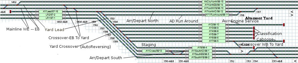 |
TrainController Switchboard Section showing Altamont Yard with labels |
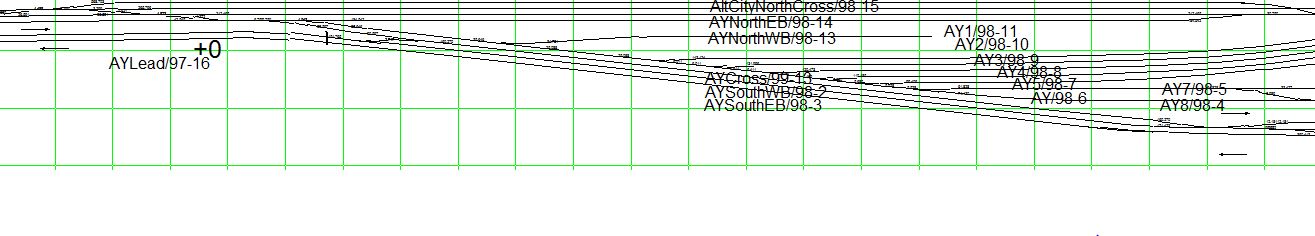 |
XtrackCAD rendering of Altamont Yard with block number labels |
As we move forward developing our XtrackCAD and TrainController Switchboard renderings of the final track plan, there are a number of areas we must visit in order create a complete plan. The bench work is one, and we will get to that in a moment. But first, let's consider a few elements of the our basic DCC electrical plan.
A Brief DCC Primer
In the XtrackCAD and TrainController Switchboard renderings above, you probably noticed many labels. These labels designate the names of turnouts and of power blocks, and each contains the unique DCC address that the particular devise labeled (either switch machine or an occupancy sensor) uses to communicate with the computer in the booster and with TrainController. If you are building a DCC layout, you will have to assign digital addresses to all of the turnouts and track occupancy blocks on your layout. I like to include this digital address in the turnout or sensor names. The name your give each component should appear on your final XtrackCAD and on any schematic renderings, like the TC Switchboard, as well. In addition you should generate master lists of all turnouts and blocks along with their physical locations and digital addresses. In order create logical, useful component addresses and names, it will be necessary to have a general understanding of how DCC works.
DCC (Digital Command Control) controls locomotives, turnouts, signals, and many other elements on your layout using a digital code encoded in to the electrical current in the track, and also in some cases, carried on wired or airborne computer networks. The outgoing command code "bundles" are generated in the DCC booster where track power originates, at the same time, incoming feedback "bundles" are inserted into the same network by various sensors on the layout and are read by the booster. In the simplest scenario, the user sends commands to the booster via a throttle device, addressing decoder chips inside various locomotives in order to control speed and direction and other on board locomotive functions, like lights for instance. The user may also address stationary decoders that control turnouts and other decoder controlled devises. In a more complex scenario, a PC is used to run custom software that communicates directly with the booster, in order to address locos and turnouts, and/or to completely automate any or all aspects of layout operations via complex logic that evaluates digital feedback from various sensors on the layout to allow the flawless running of complex multi-train schedules.
Every decoder on the layout, whether controlling a loco or or any other device, has a unique digital address. Digitized network commands and feedback information "bundles" begin with an address followed by a digitized command or by digitized feedback information. Each decoder simply listens for its address and then complies with the command that follows. The protocol for these address vary depending on which DCC system you use. Since I am using a Digitrax components, what follows will detail Digitrax protocol.
In a Digitrax system, loco decoder address are two or four digit numbers. I have set aside the numbers 04 - 49 for mobile decoders, The stationary decoders I use to control turnout switch machines and other layout devises are three or four digit numbers. I use three digit numbers for these address because, as it turns out, four digit address can only be created or recognized by computer software and are not compatible with the Digitrax throttle. (Note: you many have noticed that the turnout labels in some of the above track plan renderings are four digit numbers. These have been since been changed to three digit numbers.) I have set aside the numbers 100-150, 200-250, 300-350, 400-450, 500-550, and 600-650 for stationary decoders to correspond to 6 specific general location areas on the A&BR2). The Digitrax signal control cards also use three digit address, which we will discuss later. For the initial creation of our track plan, we need only concern ourselves with the addresses of stationary decoders and occupancy sensors. Digitrax occupancy sensors are little circuit boards that can detect track occupancy in 16 discreet electrical track sections or blocks. The address for each of these detected blocks is the board number (in this case I have set aside the numbers 95-99 for occupancy sensor board numbers) plus the sensor number of the board. So the the block address for the first sensor on card #95 would be 95-1 and so on through 95-16.
Power Districts and Power Blocks
Assigning and naming power blocks will also require a general understanding of power districts. On most DCC layouts the track is not wired directly to the booster. In most cases there are power managers and block senors in between the booster and the track. A power manager is a circuit board that acts like a little fuse box. The layout is divided into sections and each section is protected from electrical shorts by its own breaker on the power manager, thus dividing the layout into multiple power districts. With this set up, if a short occurs in a section of track, the power manager will shut down only that power district, and trains will continue to run normally on all the other districts. A logical and consistent scheme for laying out power districts and occupancy sensors is critical to the construction of a smooth-running and easy to service DCC layout.
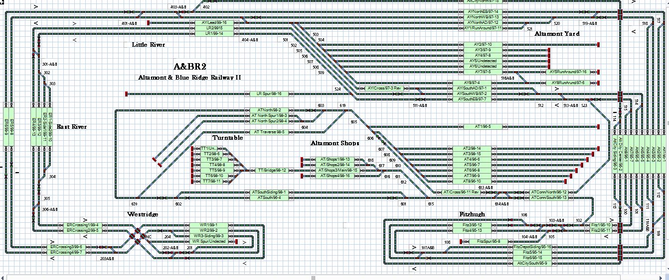
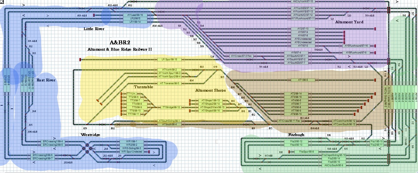
I like to keep it simple. On the A&BR2, I will have 5 Digitrax occupancy sensors (board numbers 95-99) each capable of monitoring 16 blocks of track, and each occupancy sensor will have its own power district (Power Districts 90-1, 90-2, 90-3, 91-1 and 91-2). So 5 power districts each with 16 blocks, that is 80 blocks in all. I have divided the layout into five sections: Fitzhugh-Altamont City (power district 90-1 [green] and occupancy sensor 95), Altamont Terminal (power district 90-2 [brown] and occupancy sensor 96), Altamont Yard (power district 90-3 [blue] and occupancy sensor 97), Terminal Loop-Shops-Turntable (power district 91-1 [yellow] and occupancy sensor 98) and Westridge-East River-Little River (power district 91-2 [purple] and occupancy sensor 99). Each of these sections has 16 more or less contiguous power blocks and each set of 16 blocks is a separate power district. The color coded track plan below shows this arrangement on the A&BR2.
 |
Instead of just putting detection blocks in just yards and at stations and in other places where I wanted trains to stop, I opted to place them pretty much everywhere. This is to say that any lengthy section of track between turnouts will be wired as at least one detection block. Very long track sections, might get two or more blocks. The turnouts themselves and any very short sections of track in between will be wired directly to the power district power bus and will constitute undetected routes between detection blocks. The plan is critical, so I take your time, paying attention to the logical flow of traffic through blocks as the system tracks the train around the layout and to the logical groupings of blocks into protected power districts.
Block and Turnout Names, Addresses, and Labels
So, with this little bit of DCC background, we can go ahead and create block and turnout names and enter them onto our track plan. For block names, I like to use both a brief reference to the block's location and the block's digital address. For example, the block for the depot siding a the town of Fitzhugh is called FitzDepotSiding/95-16 or the North Arrival and Departure Track at Altamont Yard is AYNorthAD/97-12. For turnout locations, descriptions can get a little cumbersome. For example, "east bound mainline to Fitzhugh depot siding west entrance" is just too much to deal with. So for turnouts, I use only the three digit address for the name. Note that this number will supply a general idea as to the the location of the turnout because I assign addresses according location. For example, turnouts in the Fitzhugh-AtlamontCity area are given addresses between 100 and 150; turnouts in the Westridge area are give addresses 200 to 250 and so on.
Make a complete list of all turnouts and block names and keep it up to date as you make changes, and then enter the names into your track plan, both on the XtrackCAD rendering where you might want to use a separate layer for these labels, and on the schematic layout track plan like the TrainController switchboard where you can use the insert-text function. Be sure to keep the block and turnout names on these rendering up-to-date as you make changes.
Later on in this planning tutorial we will make color coded labels for all DCC devices and for all terminal blocks and wires on the layout. Using lists and labels derived from a good, logical, consistent labeling scheme will greatly aid installation and the future servicing of your layout. On a big layout, things can get really complicated in a hurry if you have not been totally organized and consistently methodical in your planning.
Bench Work Drawings and Plans
When we discussed starting your XtrackCAD final track plan, I suggested that you first make a layer containing a scale drawing of the bench top so that you could overlay your track plan on top. Let's now consider how that bench is to be constructed and what its exact specifications will be.
On the A&BR2, the bench will be an open framework of 1 x 4 lumber 24 inches on center, with a 1 x 6 fascia board, and a 12 inch-wide wire mounting board attached to the bench legs behind and below the fascia board. The bench will be supported on one side by lateral 2 x 4s nailed to the backdrop wall and on the other side by 2 x 4 legs set back from the front edge of the bench. The middle section will have 2 x 4 legs all the way around. The bench top will be 3/4 inch plywood and 1/2 inch homasote where there will be large flat spaces like yards, and it will be open with plywood/homasote roadbed runners in areas where there will be hills and mountains. The construction of hills and mountains and terracing for towns and roadbeds for highways and streets will be discussed later in this tutorial.
The finished bench height will be 44 1/2 inches, and the perimeter benches will extend out 36 inches from the backdrop wall, The center section and the two turn-around sections by the door will be 60 inches wide.
The bench design is an important part of the planning process, and in addition to your track plan, you should try to develop detailed bench drawings like the ones below. Since I plan to have a number of different places in the backdrop where I can reach thorough into tunnels to clean and service track and tend to derailments (which of course only happen in tunnels), I also drew some backdrop wall sections to detail these reach-through areas.
 |
Wall and Lighting Soffit Dropdown Walls bove the edge of the bench |
 |
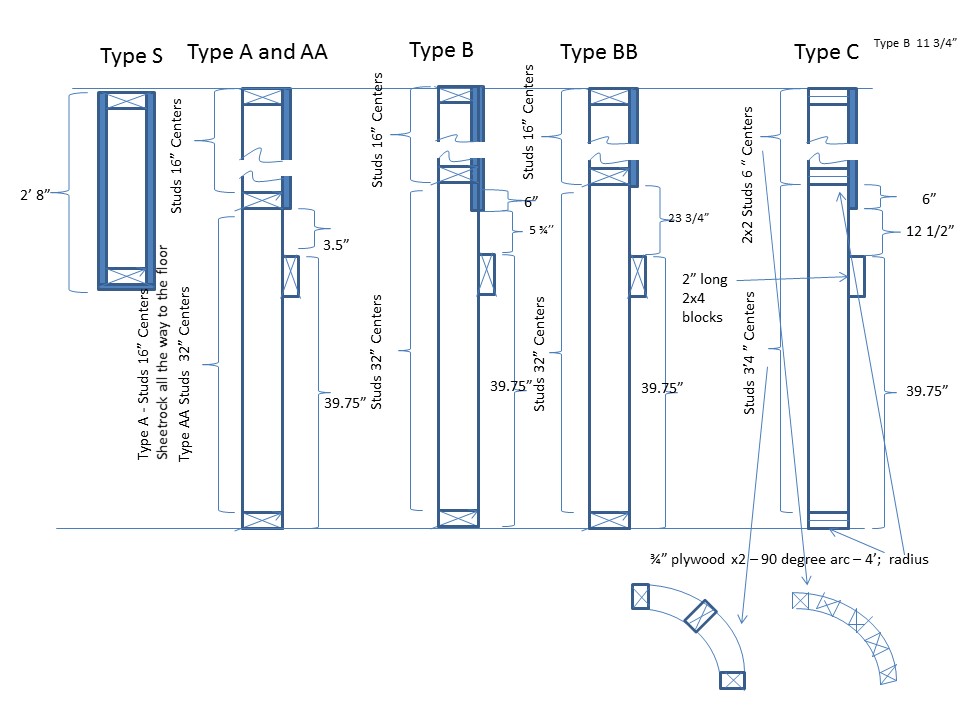
XtrackCAD wall types and bench design showing cross member supports. I use sheet rock screws to assemble the bench so I can easily move any cross memeber a few inches one way or theother if I need under-the-bench clearance for switch machines etc. |
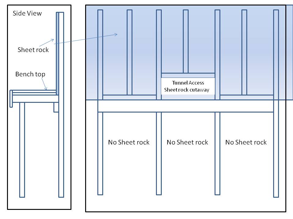 |
Basic Bench and Backdrop Wall Design |
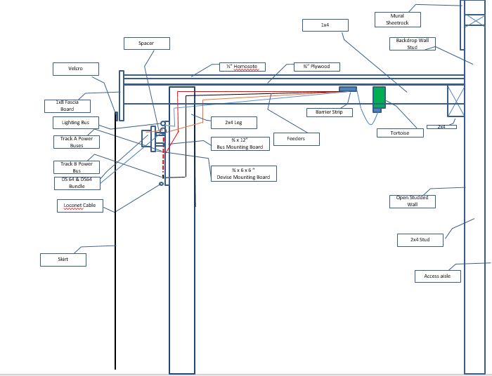 |
Typical bench section with wiring |
 |
Backdrop wall sections.detailing reach-through access. |
Access to the tunnels beneath the moutains that hide the two turn-around loops by the door is problematic. I think I will achieve a cleaner look with these mountains if they are nestled up against a higher, contoured faisure board instead of having a large radial wall protruding out into the room. I will still have some access inside the tunnel from behind the backdrop wall, although this will be more limited than in the previous design. I will probably have to make part of the mountains removable as I have done in the the corners of the A&BR1 or perhaps I can put small reach-through slots in the wide portion of the fascia and cover them with a hinged door that matches the fascia The sketch below illustrates my general intent for the entrance.
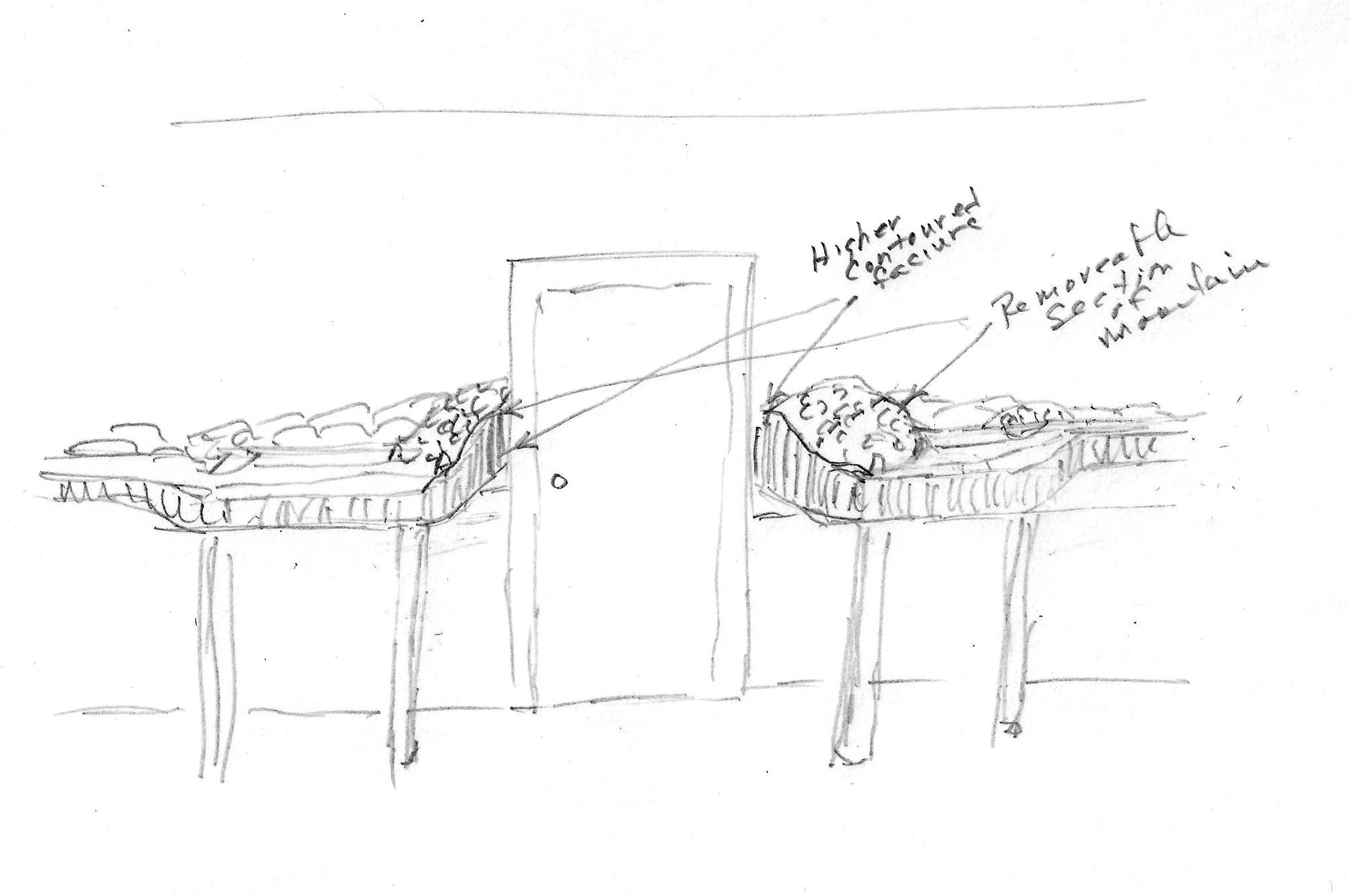 |
Entracne with higher contoured fiscia |
Another consideration is the "crawl-under-the-bench" clearance. I built a little mock-up on the A&BR1 and found that, with a 42 1/2 inch bench top, the crawl-under clearance beneath a 12 inch high board affixed below the fascia board was 25 inches, workable but pretty darned tight. The addition of another 2 or 3 inches to the overall bench height raised this clearance by 2 or 3 inches and thus made the under-the-bench crawl much easier. This added the little push I needed to induce me to go ahead and raise the bench height on the proposed A&BR2. Accordingly, I have adjusted the drawings to make the finished bench top 44 1/2 inches.
Bench Depth: A bench depth of 36 inches from the backdrop wall is a lot, 34 to 35 inches is about as far as I can comfortably reach. but if I keep all track at least 4 inches out from the back drop and use the extra 4 " to make nice transitions from scenery to backdrop, so I can go 36 inches, and I think the look on the layout will be the better for it even though it is a bit of a reach.
Plywood: Regarding plywood, two questions come to mind. Is common pine plywood sheathing sufficient, or do I need cabinet grade birch plywood like I used on the A&BR1? And is 3/4 inch plywood an overkill? Wouldn't 1/2 inch do as well?
Since all the plywood I plan to use will be covered with homasote, the more expensive grades of plywood are not really necessary for smoothness. To be sure the cabinet grade product has more layers and is thus probably less susceptible to warping, but if I stay with 3/4, this should not be a factor, so the rougher pine product should do fine. I suggest a 5 ply exterior grade with plugged and and machine sanded surfaces..
But do I really need 3/4 inch plywood for N scale, or could I use 1/2 inch? Despite the difference in cost, and the fact that the 1/2 inch will surely be easier to work with, in my mind, the question turns on the issue of warping. With bench work cross-members 12 or even 16 inches on center, I suspect 1/2 inch plywood would be fine. But I do not want to use 12 inch centers or even 16 inch centers. My cross members will be 24 inches apart! I want to be able to comfortably stand between cross-members during tack laying, and also I find that cross-members have an annoying way of constantly getting in the way of switch machines and other under-the-bench installations, so the fewer of them I can use, the better. Still, even with 24 inch centers Murphy's Law will surely dictate that there will be cross-members in the way of many switch machines, so I will just tack in the cross-member supports in place until the modules containing the switch machines are all installed. This will make it easy to move a support member should the need arise. After all the track work is complete, I will go back and secure all cross members to the frame and snug down all 3/4 inch plywood surfaces to the frame and to the cross members at no less than 12 inch intervals. Too flimsy, you say. Well, really it is not, given the fact that most of my bench work will be attached to the wall. This adds a huge amount of stability to the entire structure, and makes 24 inch centers quite workable. Some folks even go with 32 inch centers. (Note: I may use 16 inch centers on the center section, which is not attached to the wall.) Whatever the case, the upshot of all of this is this: because my 3 to 6 inch wide roadbed runners will only be supported every 24 inches, I think that it is best to fashion them from 3/4" plywood (probably a sanded pine mid-grade, not the rough sheathing, but not cabinet grade birch either). With a support only every 24 inches, 1/2" plywood runners may sag of their own weight or buckle up, I don't really know; but I know 3/4 inch plywood runners will not. I know because I used 3/4 inch plywood runners with supports from the cross members every 24 inches on the A&BR1, and I have had no warping problems, and the bench work is sturdy enough to climb on.
Wiring Planning, Drawings, Diagrams, and Schematics
Over the years I have read Allan Gartner's "Wiring for DCC" several times. I recommend it most enthusiastically.
(You can link to it at: http://www.wiringfordcc.com/wirefordcc_toc.htm) It has been my experience that following Allan's methods results in really "bullet-proof" DCC wiring. Allan recommends that every single piece of rail on the layout be solder-connected to the power buses using droppers and feeders, with no soldered rail joints, and that every turnout be modified so that power to all rail components are likewise supplied directly from the power bus using soldered droppers or soldered jumpers. It is a lot of work, but it is worth it. On the A&BR2, I plan to follow Allan's advice except with regard to very short sections of track and to the wiring of my new Atlas Code 55 turnouts where I plan to wire to the stock rails and the frog crossover only, relying in Atlas's internal connections to connect to the point rails, the closure rails and the frog rails. My reasonng here is this: the Atlas Code 55 turnouts are so delicate that I fear I will do more harm than good attempting to solder to the individual rail components especially to the pivots, so I'll trust the factory connections and make repairs if problem arise. I have found only one bad connection in more than 80 turnouts so far, and this was easily fixed by soldering a 30 agw jumper to the side of the rails that need a connection. Still, I am keeping my fingers crossed.
The first move in a good wiring plan is to make a list of the items to be wired and then decide which type, color and gauge wire you will use for each item of the list. With the exception of a little 22 agw pare-tinned bus wire, all of the wire I plan to use on the A&BR2 is stranded, insulated, so-called, primary wire. For smaller gauges you can use so-called hookup wire but it is more expensive. Also you can use solid copper wire if you like. I use stranded, because it is more flexible and less subject to breaks caused by nicking. Electrically, it should not make much difference. As to whether to twist wire pairs to cut down on electromagnetic induction and interference or not, a good rule of thumb is this: twist before a detection device, but not after a detection device. After the a detection device, the best practice is to try to keep all buses and feeders as spatially separate as possible.
Note regarding terminology: My track wire falls into three categories. "Bus wire" is the long run main trunk wire from the booster to the power manager to the occupancy sensor and from the occupancy sensors to the feeders. "Feeder wires" are the wires from the power bus to the track droppers. And "dropper wires" are the short wires from the feeders to the track. Also I refer to "detected blocks" (sections or track with the A rail wired through a discreet detection circuit in an occupancy sensor and the B rail wired directly to the power manager often via an occupancy sensor terminal blocks) and to "undetected routes" (undetected sections of track wired directly to the power manager [bypassing the occupancy sensors] on both A and B rails) .
Here is my wire list for the A&BR2:
Track bus wire: Red for A rail, Black for B rail. I use 10 agw (twisted) from the booster to the power managers and from the power managers to the occupancy sensors' circuit board terminal blocks, and I use 12 agw (not twisted - 1 inch apart) from the occupancy sensor circuit boards outputs to the track feeder wires for the A rail and from the occupancy sensor terminal blocks to the track feeder wires on the common B rail. For undetected routes, I use 12 agw (untwisted - 1/2 inch apart) directly from the occupancy sensor terminal blocks to the track feeder wires. ( I try keep the total distance from the occupancy sensors to the track under 30 feet and from the booster to the power managers and the power managers to the occupancy sensor under 10 feet).
Track Feeders: Red for A rail, Black for B rail. 16 agw (untwisted - 1 inch apart) from bus wires to track droppers ( max ~ 3 feet).
Track Droppers: Red for A rail, Black for B rail. For track in undetected routes, 20 agw (max~ 10 inches including a short service loop) from terminal block in a Tortoise Interface (see below) to a short piece of 22 agw pare-tinned bus wire that is soldered to the underside of the rail. For track in detected blocks, the dropper wire makes a small service loop and is soldered directly to a short piece of 22 agw pare-tinned bus wire soldered to the underside of the rail. (All the connections between any wire and a short piece of 22 agw pare-tinned bus wire will be hidden and protected in the pass-through hole in the bench top. These connections are accessible for service owing to the service loops.)
12 volt power bus: (brown = +, white = -) from 12 volt supply 16 agw (untwisted) on wire mounting board
Stationery decoder power (red = +, black = -) 20 agw (untwisted) from 12 volt supply to stationary decoders
Stationary decoder output to switch machine (brown = +, white = -) 20 agw (bundled) from stationary decoders to Tortoise Interface (see below)
5 volt power bus (blue = +, green = -) 16 agw (untwisted) from 5 volt supply on wire mounting board
dwarf signal red/grin LEDs and parallel layout light LEDs - 20 agw (untwisted) networked from 5 volt power bus (blue = +, green =-) to individual LEDs or from 5 volt power bus on Tortoise Interface barrier block to LEDs (see below) all with service loops
series layout light LED chains - from 12 volt power bus (blue = +, green = -) 20 agw (untwisted) to platform LED lights and other LEDs in series
loconet: daisy chained 6 conductor telephone cable to RAJ25 connectors on wire mounting board from booster to all DCC devices.
signals: using Digitrax SE8c Signal cards, signal wiring uses ten conductor ribbon cables. Each cable can control 2 double headed two, three, or four aspect signals.
To output Freiwald 4D Sound I use a standard SUB cable connected to a small outboard Surround Sound modules (xx). Speaker cables from these devices to the speakers is standard, stranded two pair speaker wire, nothing special.
Computer serial interface to loconet uses standard USB cable and a RR CirKits Loco Buffer device.
Planning DCC Device Wiring
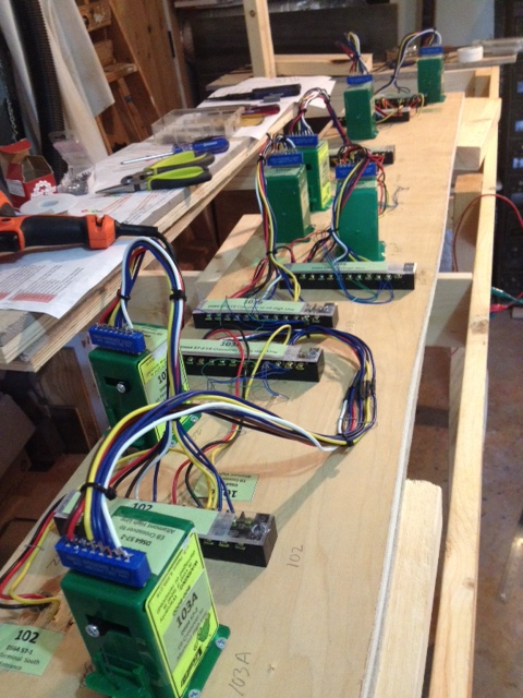
Devices: Next let's consider the DCC devices to be wired: Power Managers, Occupancy Sensor Boards, Stationary Decoders, Switch Machines, and of course, the track. A good plan will include a wiring interface and interface schematics for each these. Here are the schematics for these devices on the A&BR2 accompanied by photos of the actual interfaces, which I prefabricated while the train room was under construction. I created the schematics using ExpressSCH 7.0, a schematic design freeware application distributed on line buy ExpressPCB. You don't have to dwell on these pictures and schematics. The idea here is not to specifically show you how to wire up your DCC devices. Rather the idea here is to suggest what a comprehensive planning and documentation scheme for the wiring of these devices might entail. Notice the labels. We have mentioned them before, and we will get to them in detail in a later section of this tutorial.
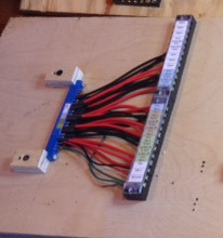
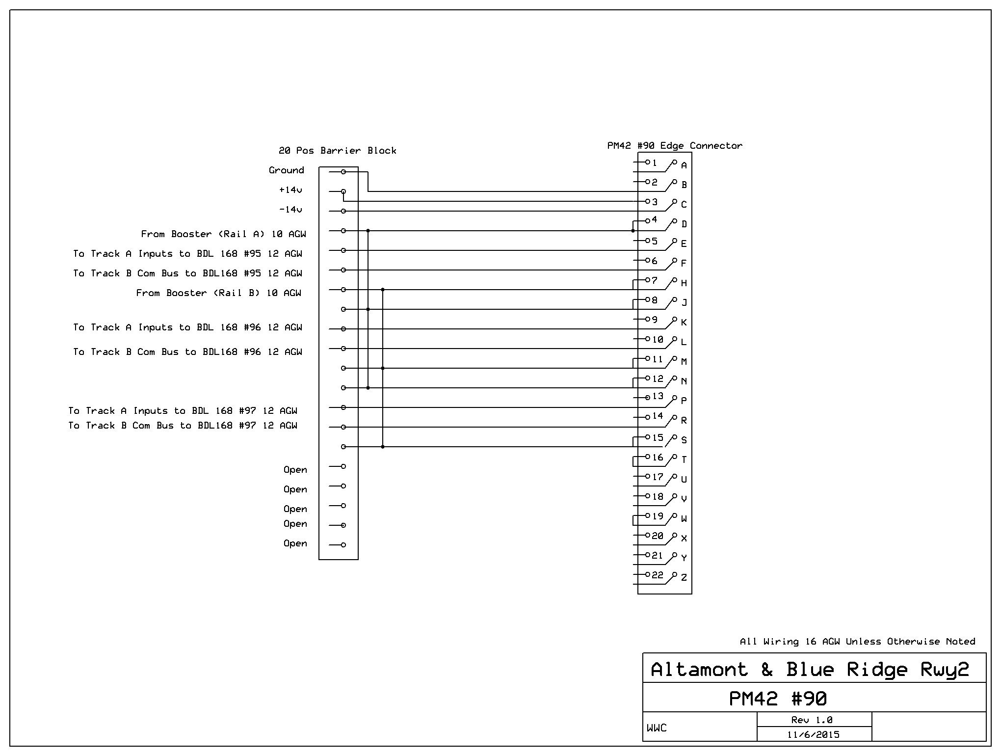
| Power manager: Digitrax PM42 22 position female edge connector wired to 2 12 position barrier blocks (red/black 12 agw) with labels and board power and ground (red/black/green 20 agw) |
 |
 |
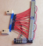
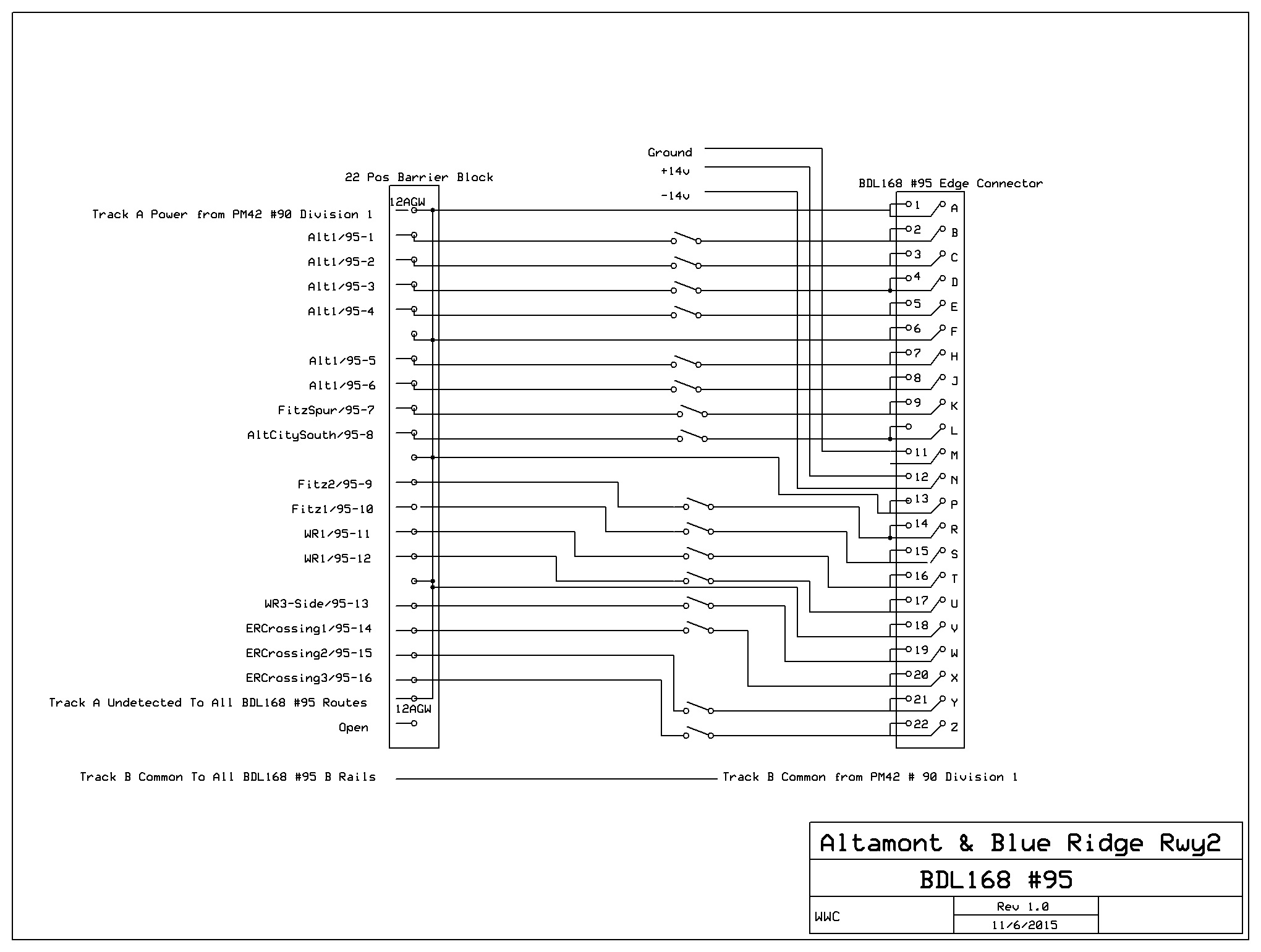
| Occupancy Sensor: Digitrax BDL168 22 position female edge connector wired to 2 12 position barrier blocks (12 agw red [track A only]) with labels and board power and ground barrier block (red/black/green 20 agw) |
 |
 |
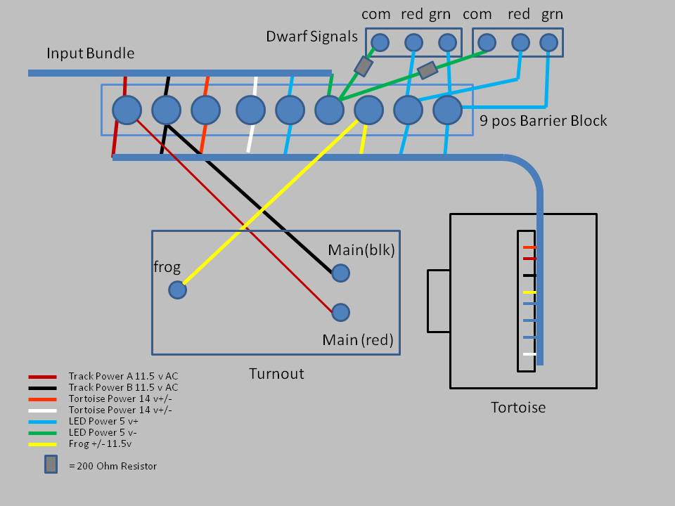
| The Tortoise Interface: with feeder inputs attached (5 volt LED for dwarf signals - blue/green 16agw feeders - 20 agw connectors and droppers; 12 volt Tortoise power - brown/white 20agw feeders, droppers, and connectors [although the feeders pictured are 16 agw]; A&B track power red/black 16 agw feeders, 20 agw connectors and droppers.) | 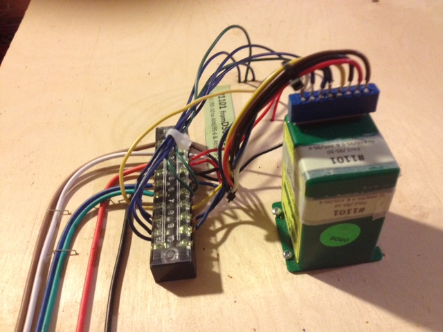 |
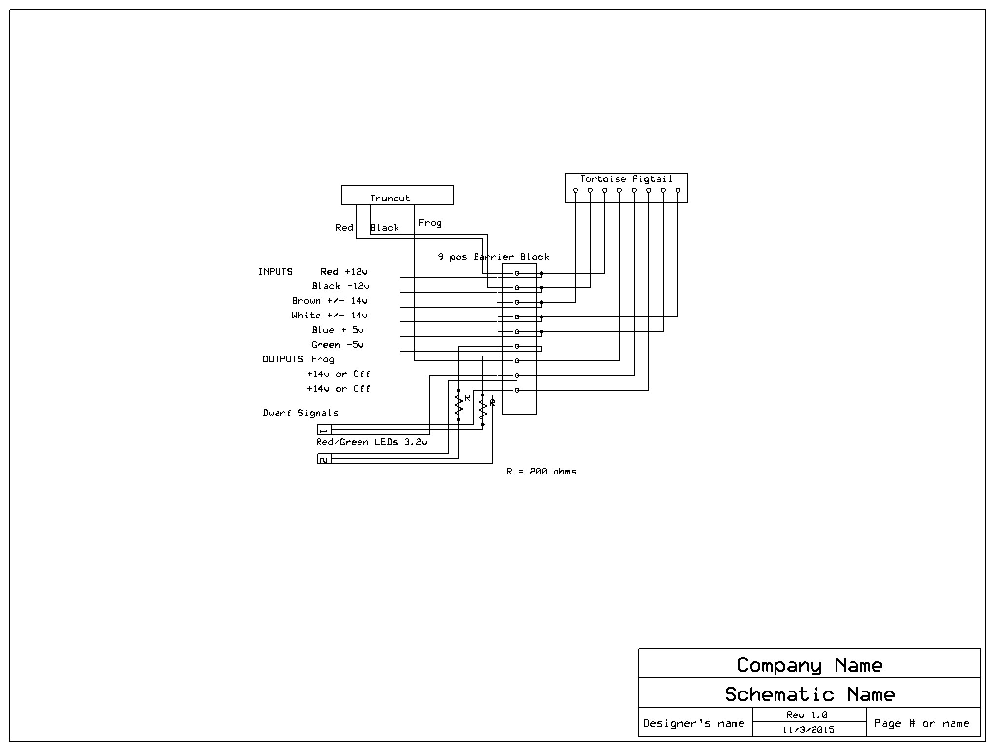 |
| Stationary Decoders and the Tortoise Interface Left: 2 Digitrax DS64s with brown/white 20 agw outputs and red/black 20 agw board power inputs and labels Right: Another Schematic of the Tortoise Interface |
 |
 |
| Two parallel undetected routes fully wired on the bench and ready to attach to feeders. I will use a single pair of track feeders from the bus and a single pair of 5 volt LED light feeders, and so I have daisy-chained all the corresponding elements on the module together. The 20 agw Tortoise feeders will all be separate discreet pairs, of course, because (except in the case of crossovers) each pair controls a different turnout. The large round holes are for mainline signals, Note I have yet to glue in ties under the rail junctions. The rough 2 x 4 s on the track side if the module are temporary guards to protect the module's track work when I am working on the bottom side. | 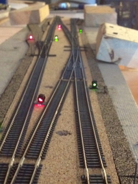 |
 |
The Bus Wire Mounting Board: I use a single 12 inch-wide 3/4 inch plywood mounting board attached to the recessed bench legs back and slightly above the bottom edge of the layout fascia board and ruining all the away around the layout to carry bus wires. This does, of course, lower the bridge of the duck-under to get up under the bench by about 8 inches, but it is worth this slight inconvenience as it supplies a neat, orderly, easy-to-label presentation of all bus wiring as well as an accessible place to mount all DCC devices.
On this board I mount the 12 AGW Track A power buses from all occupancy sensors, along with one common Track B bus, and a single undetected A power bus for turnouts and routes, as well as the stationary decoder output feeder bundles, a 12 volt power bus pair, and a 5 volt lighting bus pair, the flat signal cable, and finally the loconet cable - all spaced 1/2 inch apart. I then strategically place mounting boards mounted on spacers out from this wire mounting board to accommodate the mounting of DCC devices. On the back of the board I mount my speaker wires and my 10AGW twisted pair power cables from the booster and the power managers. So I have everything right in front of me and I can easily tap off these buses with appropriately located T solder joints to connect perpendicular feeder wires to to the buses.
|
 |
Bus Wire Mounting Board detail. Note the color coding to indicate the power district . |
There are a number of advantages to this system. First, wire spacing is the best way to head off noise and interference problems. Second it allows excellent access to all wiring and all DCC devices, and it and makes it much easier to connect feeders. Third, with this scheme, I do not have to individually wrap-label the individual bus wires (I can simply place label on the mounting board.) And fourth, it is easy to build.
Droppers: There are a number of different ways to handle droppers on any layout, so as part of the planning stage, it is good idea to workout how you plan to connect droppers to your track and light feeders.
On the old A&BR1, I used a conventional method. Short droppers made from 20 agw, solid copper, pare-tinned uninsulated bus wire were soldered to the underside of the rails and passed through individual holes in the bench top and then soldered directly to the insulated 16 agw feeders. The feeder to dropper solder joints were then covered with a plastic wire nut. This gave me a good, solid solder connection to the rails and generally worked fine, but it was a bit messy with short lengths of uninsulated bus wire exposed under the bench. It would have perhaps been better to have used solid copper red and black insulated 22 agw wire for droppers.
On the A&BR2 on sections of track and on turnouts, I will use short, 3/4 inch lengths of 22 agw bus wire soldered to the underside of the rail or to the leads of LEDs. These very short droppers will then be soldered to 4 to 10 inch lengths of insulated 20 agw primary wire, which will go to the Tortoise interface barrier blocks or simply to 16 agw feeder bus wires in the case of track or 20 agw feeder networks in the case of LEDs. Using this scheme the solder connection between the short uninsulated bus wire droppers and the insulated stranded wire dropper extensions will be inside the individual pass-through holes in the bench. These hole will have to be slightly larger than usual dropper holes to accommodate solder joints and the insulated 16 agw wire, and I will fill any gaps around the 20 agw bus wire with modeling clay to avoid ballast leakage. The clay effectively closes any gaps but remains soft enough to allow me to service the connection should that be necessary in the future.
I place a short service loop below the bench where each dropper passes through to facilitate repairs if needed. In the rare case that a rail dropper's or LED's solder connection fails (either at the rail or at the connection to the insulated dropper extension inside the bench top pass-through hole), I can easily pull up the turnout or track or LED to make the repair; or the connection can be restored by drilling a new hole next to the rail and feeding a new bus wire dropper soldered to the old dropper extension up though the new hole and soldering the new dropper to the side of the rail. With a little paint and ballast, it is easy to hide this connection. Either way, I avoid having to pull up the track or the turnout far enough to access the underside of the rail. (Note it is my usual practice to glue track down using white glue, but not to glue down turnouts. Once the turnouts are in perfect alignment, I set them with temporary track nails, which I pull up when the ballast is in place and set. With an ample service loop, it is pretty easy to pull up a turnout far enough to service a broken connection.
DCC Device Placement
I want the two Power Managers pretty close to the Booster and I'll use twisted pair 10AGW for the connection to each. Then I want the Occupancy Sensor Boards each in the center of the the area of the track they service. Digitrax recommends that a BDL168 occupancy sensors be no further than 12 feet from the Booster using 12 AGW for the connect, but on the A&BR1 I have one case where a BDL 168 is roughly 20 feet from the booster if one includes the run from the booster to its associated PM42. I have experienced no problems with this setup.
On the A&BR2, I plan to have one Power Manager right next to the booster and the second about 10 feet away. The aggregate length of the runs from the booster through the Power Managers and on to the Occupancy Sensor Boards will vary, three are well under 12 feet, one is about 15 feet, and the longest is about 20 feet. On all of these runs I'll use twisted pair 10AGW to connect the Occupancy Sensor Boards to the Power Managers, and I'll take care to keep these runs well away from any other wiring that may cause electrical interference. Although two of these booster-to-Occupancy Sensor runs are a good bit over the Digitrax recommend length, in N Scale with 10 AGW, I suspect it will all work fine. I ran this all by Digitrax technical support service, and they also think it will work fine, but of course there is no guarantee.
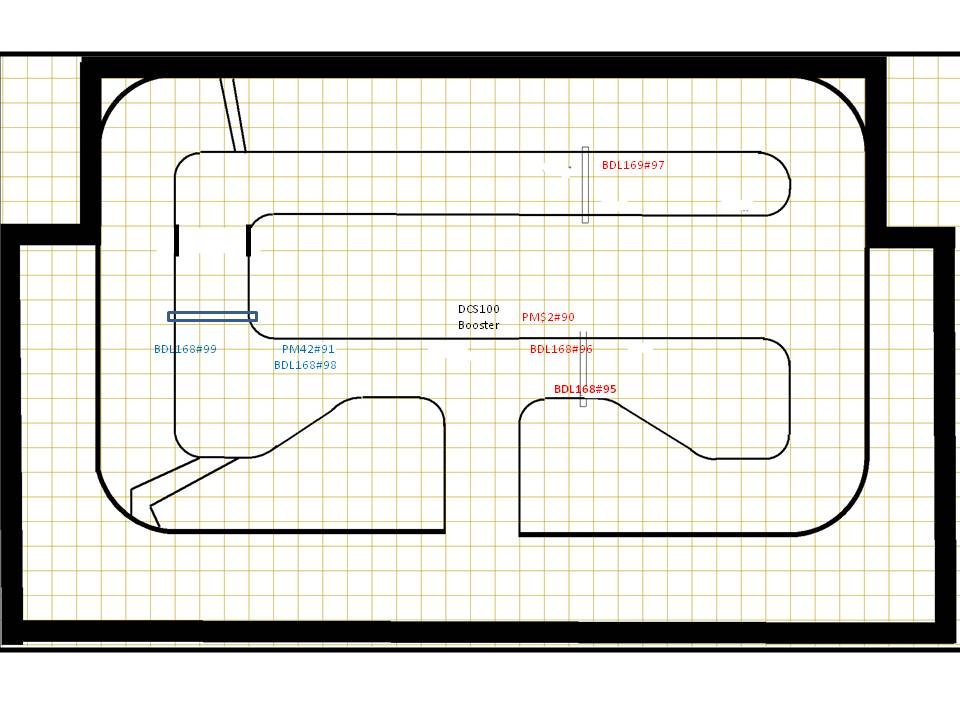 |
DCC Device Placement Each square in the grid equals one foot. |
Mounting DCC Devices
The A&BR2 will have a one foot-wide wire mounting board running all the way around the layout mounted just below and slightly behind the fascia board. To this board I will attach all of my track power bus runs from the BDL168 occupancy sensors to their farthest junction point to the individual blocks. These 12 AGW runs will be stapled to the mounting board 1/2 inch apart. This leaves ample room for parallel bundles of DS64 stationary decoder feeders, a 12 volt power bus, and a 5 volt LED lighting bus, as well as the loconet cable, all of which will be spaced well apart and well away from the track power buses. The plan is to also locate all control devices (DS64s, PM42s BDL168s and SC8s etc.) on individual mounting boards that will be mounted at various place along the wire mounting board space 3/4" above the wire runs and separated from the wires on the main mounting board below by 3/4" plastic spacers.
After I competed the wiring for the two PM42 interfaces and all five of the BDL168 interfaces, I went ahead and mounted these devices on 12" x 12" mounting board as pictured below (or on 12" x 24" mounting boards in the case of the two BDL168s that will be located right next to the PM42s).
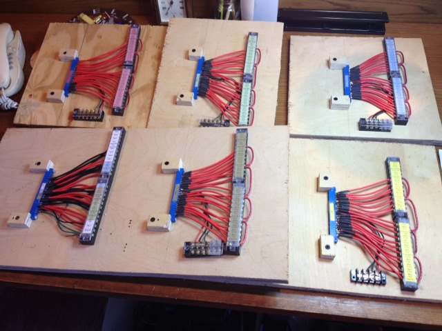 |
Top row: 12x12 BDL168 Mounting Boards Bottom row: 2 overlapping 12x24 PM42/BDL168 combo Mounting Boards |
Let us now turn our attention to a simple mounting board for the DS64s Stationary Decoders that will control Tortoise Switch Machines and crossing gate flashers. These will be mounted all around the the layout on mounting boards similar to the BDL168 and PM42 boards, that is, they will be mounted on the 12 inch-wide wire mounting boards that will run all the way around the layout, positioned 3/4 of an inch above the wire runs using plastic spacers on the mounting screws. Most of these will have only one DS64, but some, like those associated with large yards will have several. For the prototype, I chose to create a board with two DS64s.
Whereas I think it best to power BDL168, PM42s, and SE8c boards individually using the little, 14 volt, 300ma PS14 sold by Digitrax, on the A&BR2, I will employ a fused, 16 AGW, 12 volt, 6 amp power bus (similar to the bus I will use to power LED layout lights) to power the DS64s. This will keep things nice and neat and avoid a tangle of power supply wires. Note that with a 6 amp bus like this, it is a very good idea to make sure the circuit is fused to avoid any overheating.
Because of the size of the connectors on the DS64 and because I am am not worried about power loss as the distance to the switch machines are short, I decided to use 20AGW feeder wires from the DS64 to the Tortoise Switch Machines. The finished prototype is pictured below without the loconet cables, which, in order to avoid crosstalk interference, run out of the opposite side of the device from the feeders and will pass though their own, separate exit hole, which will be drilled in the upper left corner of the board as pictured:
|
Stationary Decoder Mounting Board, pictured without the loconet cable. |
Planning LED Lighting Circuits
On the A&BR1 I used Christmas tree lights (6 in series) powered by a separate 12 volt DC supply. On the A&BR2 I plan to use LEDs (5mm for structure lighting, 3mm red/grin for dwarf signals, and 3mm warm white for platform lighting. The planning for these circuits is straightforward, but it is important to work it out before hand, and to build prototype circuits and test the LED bulbs you plan to use in order to get the exact brightness you want by selecting the resistor value you will use how much current you will need. For this I use a standard bread board as pictured below.
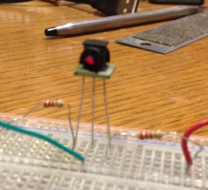 |
Bread Board test circuit for red/grin dwarf signal LED. With 200 ohm resistors each bulb draws about 10or 12 ma. Green leg is electrically a little different from the red. |
On the A&BR2 I will have 16 agw 5 volt (blue/grin) and 12 volt (brown/white) power buses running all the way around the room on the wire mounting board. For layout structure lights I will use the 5 volt supply and 20 agw (blue/grin) sub-buses with each bulb wired in parallel with a 200 ohm resistor attached to one leg of the LED. For the red/grin LED drawn signal lights, the sub-buses will come off the Tortoise interface and again all of the LED bulbs will be wired in parallel each with it own 200 ohm resistor attached to the common return leg of the LED at the Tortoise Interface barrier block.
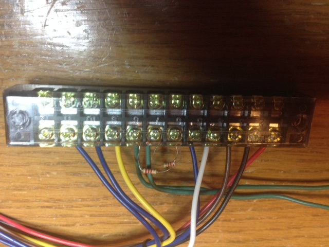 |
Tortoise Interface Barrier block with 2 red/grin LED lighting resistors in place |
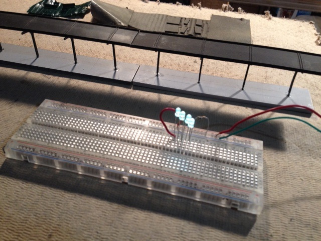
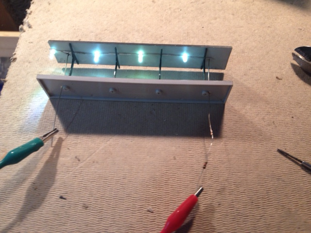
For platform lighting, I'll use the 12 volt supply with sub-buses each feeding four 3mm warm white LEDs wired in series with a 860 ohm resistor.
 |
 |
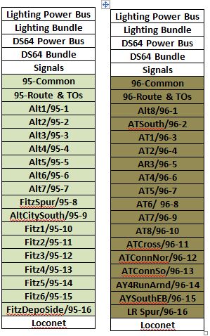
Lighting labels will be affixed to the underside of the bench at the tortoise interface or where the penetration is made for each LED or to each in LED series chain. Also a label listing all the LEDs supplied will be attached on the wire mounting board where each 20 agw lighting sub-bus attach es to the main 16 agw 5 volt lighting supply bus or to the 12 volt bus as the case may be.
DC Power Supply Planning
If you plan to use auxiliary power supplies for lights or to power DCC devices, a little planning is in order. Here's what I did on the A&BR2.
I have a Meanwell RT-125 (132 watts with three outputs: 5 volts -15 amps, 12volts - 6 amps, and 12 volts - 1 amp) cost about $38. I plan to split the 5 volt output into two legs, one switched of/off for LEDs for structure lighting and one always on for dwarf signal red/green LEDs (individual bulbs wired in parallel each with a 200 ohm resistor- each will draw about 12ma). The 12volt - 6 amp output will power 22 DS64 stationary decoders (each will draw no more than 300ma), and a few in series chains of LEDs (each chain will draw about 20 am). I plan to run these three unswitched and three switched power buses all the way around the layout on the wire mounting board and pick off of them with feeders as need be.
I began by thinking about where to mount the supply and how to route the aux power buses. I concluded that a mounting board with two 8 position barrier blocks mounted on the wire mounting board under he city of Altamont and adjacent to the center of the long middle section would work best. From this point, I can plug the supply into one of the under bench switched layout power outlets, and I can run 8 (4 switched and 4 unswitched) buses out from the 5 and from the 12 volt output barrier blocks: two for the long run to Altamont Yard, Little River, East River, and all the way around to Westridge; two down each side the the center section, and two to Fitzhugh.
I made a little schematic to document the hook up and a photo of the wired up supply on its own mounting board.
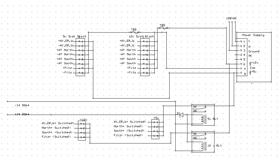 |
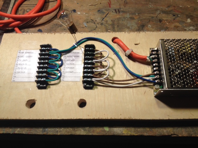 |
Planning the Overall Flow of the Landscape and Tweaking Track Elevations
As previously discussed, when modeling in N Scale, especially on a large layout, one can create remarkably convincing panoramic landscapes. Indeed, I contend that the central focus of modeling in N is not so much creating individual detailed "scenes," like in HO, but rather the overall flow of the terrain through which your railroad travels. Whatever the case, in any scale, creating convincing scenery takes considerable planning.
With a refined track plan and a plan for the bench work and a good wiring plan all beginning to emerge, we can now begin to think about details like roads and fields and locations for structures, as well as about hills and mountains and the overall topography in general. As your thoughts begin to gel on the size, the form, and the placement of these features, you may need to tweak your track plan to match track elevation to the terrain and to achieve realistic effects. The central focus of this kind of thinking is this notion: even though on a model railroad one builds the roadbed and track first and then adds the topographical features later, in the real world it is the other way around: the topography came first, and the railroad later altered it to suit its needs. This is a critical principle: when designing scenery, one should continually ask, "What did the landscape look like before the railroad was built?" Continually trying to answer this question should result in an interactive design process in which track roadbed routing and elevations, roads and towns, and topographical forms ... indeed all the model's elements ... interact. Mountains are not simply placed beside the track, but rather the track slices through the hills in "cuts" and traverses the valleys on fill. In this kind of design process, nothing is ever "engraved in stone" before it is built. Everything is always changeable and in flux. With this kind of approach one allows for both a well-thought-out initial plan AND a plan that can change as it is built.
The first consideration to consider regarding the new design we have already discussed: "Try to avoid running too much track parallel to the edge of the bench work." Likewise, the second consideration has also been already been breached. This concerns curve radii: to wit, even though my 30 inch mainline curves are generous, they are much tighter than their prototypes, and so they will never look exactly right, especially when carrying 70-foot-long passenger cars. So I like to hide at least parts of any unrealistically regular 90 degree and 180 degree turns and curves in tunnels. Fortunately, the offending curves are all in the corners of the room and in the "turn-around" dead-ends of the bench work ... natural places for mountains. Here is the initial rough topo form we created a the beginning of the track plan creation process showing general locations for mountains and other high ground and a few main roads and rivers:
|
Rough Elevation Topo with track plan. Dashed lines indicate track in tunnels. Note the green shading was not done with in XtrackCAD. It was overlayed on a JPG file exported from XtrackCAD using GIMP, a freeware drawing and photo retouching application. |
At this point, things were beginning to take shape topographically in a very general sort of way. That is so say, we at least established what the topography looked like before the railroad and towns were built. Now, let's create cuts into tunnel entrances and some stepped terracing on these hillsides to accommodate the streets and buildings of the towns, effectively excavating the terrain just the way it might have happened in the real world. The end result will be a great deal more real looking than it would have been had I simply built the town on the flat and placed a mountain next to it.
At this stage, planning is still of a somewhat general sort - still just a suggestion of where roads may need to go to service trackside structures and where mountains may need to be "graded" to create terraces for mountain towns. This will all undoubtedly change and become much more defined as I progress into the construction phase, but for now I am only considering functionality so I can begin to visualize things from a macro point-of-view and set final track elevations that work with the topography while at the same time honor my maximum grade specifications. Also, now that I have an idea of where the roadways will go, I give consideration to the location of crossing signals and gates as well as make decisions regarding signal placement once I have finalized the exact locations of all detection blocks and turnouts.
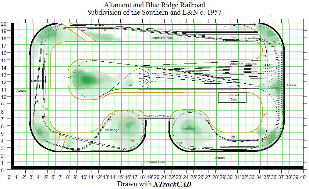 |
Topo with track elevations |
Notice in the above schematic that the numbers +0, +2, +5 etc. are indications of track elevations at various key points. I have purposely omitted indicating road or town elevations as they will be determined by the topography and by nearby track elevations. Roads are much more flexible with regard to turn radii and elevation changes than track, so I usually follow a rough plan and tweak it as I build topography, laying in 1/2" homasote pads and terraces (designed to accommodate the footprints of structures or groups of structures) and homasote strips for highway and street roadbed all of which will be built right into the homasote framework of the future topography. (Much more on this later, also see the tutorial "Shaping the Landscape" in the "Tutorials" section of this website.)
|
A more complete topo with roads, and suggestions of town terracing and rivers and streams. Note that, at this point, I have not indicated the steet locations or the terrracing for the City of Altamont, which will be constructed along the righthnad wall of this rendering. Still, all track elevations have, at this point, been entered into XtrackCAD, but are not discernible in this overview rendering . |
Bridge, Viaduct, Overpass/Underpass, and Culvert Planning
As we have noted, in the beginning only a general sense of where mountains and streams will be is required in order to effectively tweak track planning. Again the exact forms are best worked out as roadbed is layed out. This may seem imprecise, but I have found that too much prior on-paper, two-dimensional planning with regard to landscape and structures is often a waste of time. It can even get in the way. The fact is, I'll almost always make changes as I see things begin to come together in the real three-dimensional space.
One notable exception to this kind of loosy-goosey initial approach to planning for structures, roads, and topography is bridges. It is critical that an initial plan include the description, dimensions, span, height, clearance, and location of all bridges, overpasses, culverts, viaducts, and crossings in order to ensure that track plan elevations correctly conform to the requirements of these structures. I like to purchase, assemble, and weather all my bridges before the roadbed is laid down. I then install them along with any abutments and piers or pilings as the plywood/homasote roadbed runners are constructed. As this is done, I get a good feel for exactly how the scenery and topography will work around and under each bridge and the look of the landscape where each bridge is attached to the layout.
In the present case of the A&BR2, I have made a list that details the specifications of the14 bridges that I have on hand from the old A&BR1, the descriptions of the any bridges I plan to purchase, and a track plan detailing where each will go in the A&BR2.
ON HAND from A&BR1 (green on drawing below)
2 cornerstone double track truss/10 X 2-3/4 X 2-3/4"
1 cornerstone double track contrete overpass 13 7/8x11x5 1/12 .
2 kibri single track arched 34.8 x 5 x 4.7 cm
2 single track volmer arched /6-1/4" x 1-3/8"
1 single track cornerstone tressel
2 Micro Engineering N 75-150 80' Open Deck Girder Bridge Kit / span 6 inches
1 Monroe Models N 9005 Concrete and Girder Bridge Kit (High Density Hydrocal)/ 1-7/8"+ expansion/ H x 6" L x 5" W
3 plate girder (these are code 80 NFG for ABR2)
Need New (red on drawing below)
1 long arched double track steel bridge - Faller N 222580 Bietschtal Bridge -MTS 71.99 594x69x131mm
2 double track code 55 plate girder (plate girder bridges on A&BR1 are code 80 - need code 55) use Atlas N 2081 Code 55 Double Track Through Plate Girder Bridge MTS 14.99 Double Track - 6" x 2-5/8"
1 country road wooden overpass - Monroe Models N 9007 Country Road Bridge MTS 29.19 9-1/2" L x 1-3/4" W x 2-1/4" H
2 Kibri straight stone viaduct (Note 2-16-2016 :This will not work on curve need - substitute double track palte girder ) 7-1/2 x 1-1/2"
Pier type risers for the 2 curved crossovers of the Altamont City single track overpasses. Custom built from 2 Micro Engineering N 75-519 320' Tall Steel Viaduct with Standard Bridge Kits. 24" x 8-3/16 with a 3-1/16" wide x 3-1/4" tower footprint.
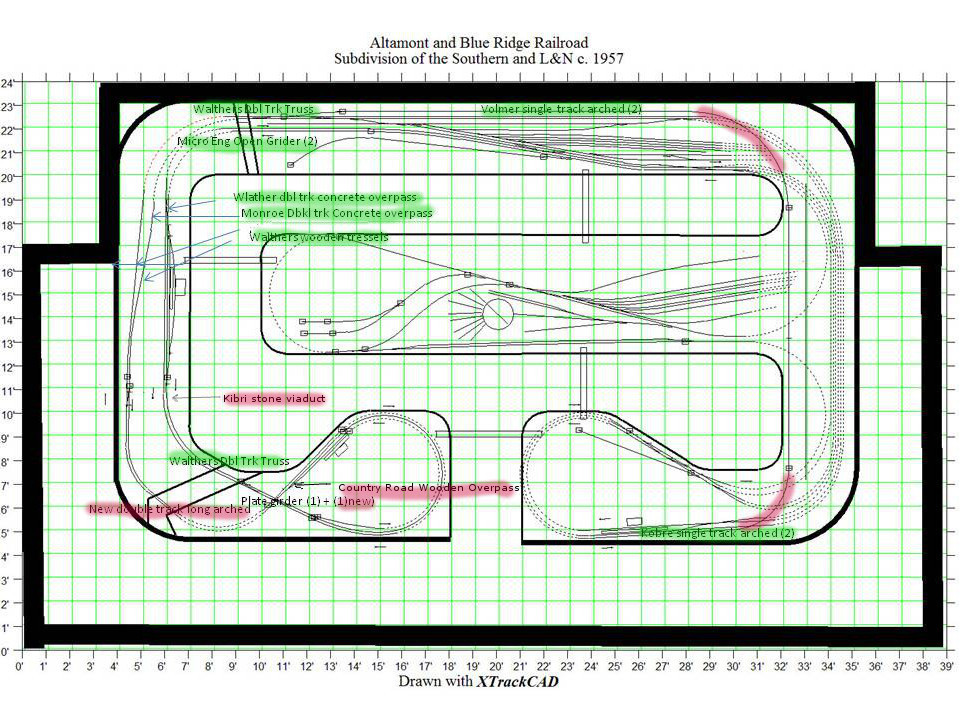 |
Track plan with bridge locations red = New - to be putchased green = on hand. |
Mainline Signal Placement
Mainline signal placement requires careful planning and a great deal of thought. It is best to begin by sketching out something rough and then tweaking it as you go along. Once you have a general plan that seems to work, enter enter the sketched mainline signal plan onto your schematic master plan. I use TrainController Switchboard. Although stylized and not to scale, this switchboard offers the most clear and readable representation of my layout.
There are a lot of of ways to approach signal placement, and a purist/prototypical approach is, in my opinion, not always best. For one thing, it difficult to define what is prototypical when so many rail systems in the US and worldwide use any so many different signal protocols and varied sets of operating rules. On a DCC model railroad, as on many real railroads, block occupancy and turnout position are generally the keys. In this regard, signal placement is of foremost importance, and it is necessary to first devise a complete protocol and a full set of operating rules in order to place and program signals in a way that consistently indicates the status of the track ahead.
I am generally pretty happy with the set up I have on the A&BR1. I use Digitrax SE8c cards to control 3 aspect, double headed signal masts. That is each mast has two heads each with three lights (red, yellow, and green.) I can control 16 masts (32 - red/yellow/green heads) with one Digitrax SE8c card. Signal programming in TC can be complex, but both the wiring and the installation of the masts is very straightforward thanks to Digitrax's use of 10 conductor ribbon cables between the SE8c outputs and the individual masts.
In general, the system protocol I use on the A&BR1 and will continue to use on the A&BR2 is this:
1. The upper signal head on each double headed mast is for the mainline track; the lower head is for the diverging track.
2. If the diverging track goes off to the right the signal will be placed on the right of the mainline track; if the diverging track is on the left, the signal will be placed to the left of the mainline.
3. Red means either the bock ahead is occupied and or a turnout between the signal and the next block is thrown in a way that will derail the train.
4. Yellow means the next block is free but the block beyond that it is occupied and/or a turnout after the next block but before the subsequent block is thrown in a way that will derail the train.
5. Green means both of the next two blocks are free and all turnouts before the second block are in safe pass-though positions.
6. Other than the dwarf signals, which reflect turnout position only, I will not use signals in yards, so these rules apply only to main lines.
So with a double tracked mainline, like the one of on the A&BR2, signals will generally be placed just after the stop marker at the end of a block oriented to the direction of travel only. In certain cases, where there are crossover tracks, there will be signals on a single track in both directions. If there are a lot of turnouts or crossovers in the route ahead before the next block or in the route beyond the next block, this can get a little hairy to program, but once programmed, it all works nicely with TrainController. If the stop markers are set near the end of a block as they generally are, one can observe a train on a automated schedule stopping to observe a red signal, and then continue on under yellow when the block ahead clears. To get this all right, signal placement is key. One of the best tools for visualizing where to place signal masts is the TrainController switchboard. This simplified, stylized, linear block and turnout diagram makes it easy assess all the possibilities of signal placement, traffic flow, block occupancy, and turnout position in any given section of the layout. Here is the Fitzhugh section with signal icons in place:
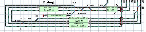 |
Each green signal head in the rendering at the left represents a 3-aspect signal head on the layout which might be either green, red, or yellow. In most cases signal masts will have 2 heads, but there will be some single-headed masts like the one in the westbound block Fitz6/95-15. Do not be distracted by the signal symbols at the ends of the bocks themselves, these represent aspects of block function and have nothing to do with mainline signaling |
Train Room Lighting Planning - Daylight
Trainroom lighting can be as simple as a single overhead room light fixture and a wall switch, or so complex as to require and engineering degree to understand it. In this tutorial, I will discuss the lighting on both the A&BR1 and the A&BR2 in an effort to suggest the kind of planning that goes into flexible and highly realistic model railroad lighting schemes. Again, this is just the way I do it, and as before I suggest that you go on line and read all you can regarding trainroom lighting. There are any number of good appraoches, and the way I do it may not be the best for you. Still, I highly reccomned my lighting scheme, and an understanding of how and why I do it this way will inform your thinking and will also detail the planning process for any scheme your may choose.
Just like the track plan, the way to begin is to examine the space, amke lists, and ask yourself questions. How many lights will I need? How bright should they be? What type of light should I use? What will the spacing between fixtures be? How will they be switched and where? Do a I want to hide the fixtures from the viewer? Do I want computer control of my room lights. Will there be accent lights with colors? If so, how will these be switched and controlled?
On the
A&BR1, I had eleven 4-foot-long, single-bulb, dimable, daylight,
fluorescent
fixtures with UV bulb filters, all hidden from view in a deep
sofit
above the
bench-work. Each bulb putst out about 2700 lumins. Ultraviolet filers
are a
necessary part of any florescent setup, becuase without them
flourescents will fade the colors of your scenry over time. I was
delighted with this set up. The lighting
produced by these extremely bright bulbs is warm and bright, and it
looked great,
but there were a few
flaws. As you can see in the drawing below, outside
of the lighting sofit I had conventional
track lighting - two dimable circuits. I originally planned to use
these
for a kind of hot-side/cool-side colored light to add depth and create
twilight etc., but
although the colored incandescent track light cans, when angled toward
the
layout, cast nice realistic
shadows on the ground, they also cast shadows on the backdrop which
is not a desirable effect. So on the A&BR2, I mounted my effects
lights inside the sofit where I could angle them
only slightly aimed away
from the
backdrop.
 |
On the A&BR1 I had track lights outside the sofit angled toward the layout. The warm fluorescents looked great and give plenty of light.but 65 watt can lights cast shadows on the backdrop. |
The florescent lights I use operate in a
Lutron system of dimable
florescent ballasts. I know that when I say "florescent", there are
those
who will wince, but really, you have to see this particular
installation. It looks great!
This system has a number of things in it favor:
1. The quality and warm color of the light produced by the
Sylvania F32T8-835 T8 tubes is excellent - quite realistic indeed. It
is warm and difuse, and these bulbs produce virtualy no shadows at all.
2. These tubes are economical to operate, and they put out A LOT! of
light - 2850 lumens each. With the lights all the away up, it is
indeed broad daylight on the A&BR.
3. The dimable ballasts are a bit pricey (about $174 each - one ballast
can run three single-bulb fixtures. ). Still, lumen for lumen this
is a
very economical system, and the Sylvania T8s last
24000 hours! I have 11 fixtures on
the A&BR1. I'll need 7 more on the A&BR2.
4. One can employ reasonably inexpensive (about $10 each)
tube covers to filter out the ultraviolet
part of the spectrum, and thus avoid the color-fading that comes with
fluorescents.
On the negative side:
1. In the lowest position, dimmers do not fully turn off tubes, but
they go down to 1%, which is acceptable.
2. These florescent dimmers are not programmable, and I have
found no way to interface with the internal electronics to make them
so.
It is just beyond my depth. So I have to resort to a mechanical system
that moves the dimmer sliders using computer controlled servo motors.
(This works fine.)
3. The installation of the ballasts is on the complex side, and it
takes a good
electrician. These can be a little costly to install compared the
convention
fixtures.
Mechanically moving the dimmer sliders up and down using servo motors is accomplished by a program I wrote for an Arduino microprocessor which executes dimming sequences triggered by inputs from the computer via commands to a DS64 stationary decoders. It's was a little bit of a Rube Goldburg, but it worked fine. Still, in an ideal world computer addressable fluorescent dimmers would be very cool.
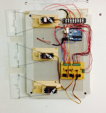 |
Receiving input from stationary decoders, Arduino controlled servos mechanically moved room light dimmer sliders on the A&BR1. A bit of a Rube Goldburg ... but it worked fine. |
On the A&BR2, I have improved the trainroom lighting dimmer control system. I have eliminated the DS64 and the Arduino, and I now control room lighting servos with dimming programs that I write in C#. These little program send string serial commands over a USB to a servo controller board (SSC-32). The individual programs can be called from Traincontroller using automatically triggered push buttons using the "Execute" option in the each pushbutton's operations window. This way I am able to address and operate and automate multiple servos simultaneously. I have also developed a better way to mechanically move the dimmer faders with servos using small tension rods with clevises on the ends. Below is a drawing detailing the new mechanical interface.
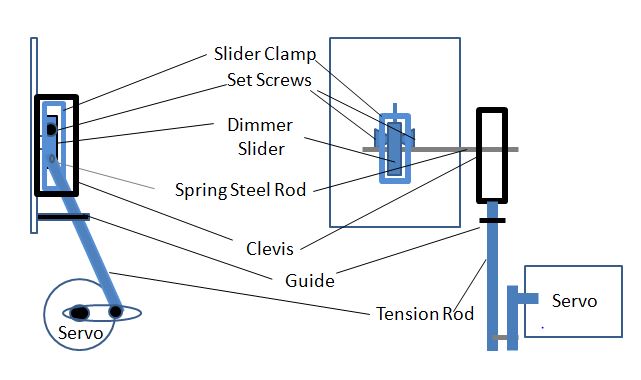 |
Improved mechical dimmer interface |
Below is a photo of the SSC32 Servo Controller Board with one small servo attached. The servos are powered by an external power supply that plugs into the jack next to the two switches on the lower left of the card in the photo. In this setup, the SSC32 is powered by a 9 volt battery. When the SSC32 is installed permanently on the A&BR2, the battery will be replaced by external 9 volt supply.
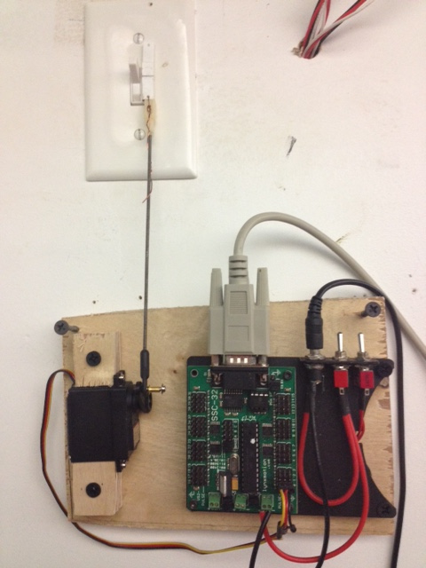 |
tUSB dimmer control with SCC32 Servo Contro Card and my improved rod and celvis mechanical interface. |
More Train Room Lighting Planning - Considering Alternatine Systems and Effects
When I desinged the A&BR2, I spent quite a bit of time looking at alternative lightng options including the new LED lighting control technologies. Using 10 watt, 800 lumin LED floods, would be perhaps just a little cheaper and much simpler to install than the florescents, and they would run on a smaller wattage dimmer. Still, I would need 60 of them to get the same light output I will get with 18 fluorescents T8s (18 T8 at 2750 lumins each = 49000 lumins ~= 60 10 watt LED floods at 800 lumins each = 48,000 lumins.) LEDS work better with a dimmer than fluorescents do. Fluorescents only dim down to 1% and require occasional adjustments, while LEDs dim virtually fully and are quite stable. The 6500 Kelvin fluorescents I use give a lovely daylight, but I can get LEDs that put out 6500 Kelvin as well. So at first the LEds looked like a good alternative, but after a little experimentation, I found that the problem with the LEDs is shadows. Even if I have an LED light every foot and a half or so, they still cast multiple light shadows on the bench top, whereas the fluorescents give a nice, realistic, diffuse, noontime light with virtually no shadows at all. So I decided to stay with the flourescents.
In my research, I discovered a system called HUE made by Phillips, which appeaded to me to me the perfect highlighting and colored effect lighting compliment to my flourescents. This stuff is impressive indeed, for it gives wireless computer control (via WIFI) down to individual fixtures, not only in matters of brightness, but in matters of color. The possibilities are endless. It uses ZigBee protocol, and I can write Windows applications to give me complete control.
I decided to install simple incandescent fixtures for hue bulbs between the flourescent fictures (ie. 4 foot intervals) in the soffit next to the backdrop wall and angled slightly toward the aisle edge of the bench work. This would avoid any shadows on the backdrop and give me the color changing capability of the HUE lights for effects. Using this approach cuts way back of the cost of the HUE bulbs required since I am using them only for accents, and allows the fluorescents to "fill" any shadows cast by the more direction HUE bulbs (except, of course when the fluorescents are very low or off - in which case - like at sunset - the shadows would be desirable.
After studing a C# light control library called Q42, I began by writting a little application to test all the Q42 commands for brightness, color, saturation, on/off, etc., and I used this to fool around with bulb groupings. I then created a stunning sunset application that addresses both flourescent dimmers and HUE lights and can be called from TC. As the main florescent room lights go down, my new application slowly fades up the HUE lights while slowing changing their color to a deep red/orange, then when the room lights are completely faded out and everything is aglow in red, the red/orange HUE lights slowly fade away and morph to a soft and very dim blue/violet starlight. Vey cool.
There were a few issues. 1) Initially I was not able to use the new bulbs on ABR1 layout in tandem with the florescent room lights because the HUE bulbs had a very limited range. In the train room, my phone gets wifi from my router just fine, but the HUE bulbs don't, so had to install a router repeater. The published range of these bulbs is 30 meters from the router, but if there are any walls etc. they don't come close to that. 2) When commanded to go to a brightness of "0", the HUE bulbs, get pretty low but do not go all the way off. This is a problem with most dimmer systems for CFL and LEDs, but given the ability to change colors, changing the color of a "0" brightness bulb to a a soft blue/violet, gives a lovely very dim nighttime effect that is actually more dramatic than complete darkness. I could, of course, program the system to simply fade to "0" and then turn the lights off, but the transition from "0" to off is a little jarring. I say "a little" because when the HUE lights are commanded to turn off, they do not just turn off, they actually execute a nice ~ one second fade. 3) The way this system handles color, is pretty messy. One can program color changes using RGB based commands which are six digit strings incorporating 3 pairs of two digit hexadecimal numbers. UGH this is cumbersome in "for" loops! Or one can use a somewhat baffling x,y coordinate system. Either way, fades across large portions of the color spectrum are tricky, because not all of the RGB or xy colors are producible by the HUE bulbs, and if you enter coordinates that the bulb can't produce, it will simply ignore the command. This is going to take some more study and some getting used to. 4) The configuration of "bridge locator" routines in Q42.HueApi is still something of a mystery to me. I was able to get things running by using a crude software tool provided by Phillips to register with the bridge and then get the randomly assigned username back for the the bridge. I then typed this username and my ip address into to my code to connect to the bridge. Since this will be a single user device, I really don't see this as a problem going forward. 5) There might be timing issues with some future routines. Phillips recommends that commands be at least 500 ms apart and 1 second apart for commands to groups of lights. This does not present a problem for the kind of slow fade ins and outs I require. I just use a loop to move from a brightness of 255 (all the away up) to a brightness of 0 (minimum) decreasing the brightness in increments of 5 or 10 with a 1 second delay after each. So a fade lasts either 51 or 25.5 seconds - smooth as glass. To produce a faster fade, I would have to make the delays less, which could cause problems, or make the increments larger, which might make them visible and kind of jittery looking.
In all, the HUE system and the Q42 API together are nothing short of wonderful - very flexible and powerful (although not totally transparent) systems that are every bit of what I expected and more! The only problem is the timming issue which limits my ability to accomplish anything except very slow fades. The error trapping in the Q42.HueApi is excellent, and it usually not only defines errors, but suggests a fix.
As I progressed, I figured out the Q42.HueApi bridge locator and start up protocol and syntax, and devised ways to use short (1 to 2 second) pauses in my dimming and color-change programs to avoid potential problems created by the slow-response limitations on the system. I am currently changing color using six-character strings incorporating three pairs of two place hex digits to address color via RGB number. I am certain that there is a more elegant way to address color change, but for my purposes, this works fine.
All the electrical in the new train room will be switched at a control panel by the computer control panel except for the power to the HUE lights. There will be one light switch by the door to turn on the HUE lights, which will always come up full daylight white after being turned off at the main switch. The main switch panel will be mounted vertically on the bench work next to the computer control desk. From this panel I can power up AC to everything, computers, DDC boosters and peripherals, including room lights, sound system, servos and servo controllers, and all of my power supplies for layout lights, dwarf signal lights, and stationary decoders.
After you have made all of these consideration your should develop a comprehesive plan. The lighting and AC electrical scheme for the A&BR2 appears below. This reneding was made by exporting a jpg of the walls and the bench design with deminsions and a one foot square grid and then inserting the jpg into Power Point and using that application draw fixtures and outlets over the top, and then finally exporting a finished jpg from Power Point.
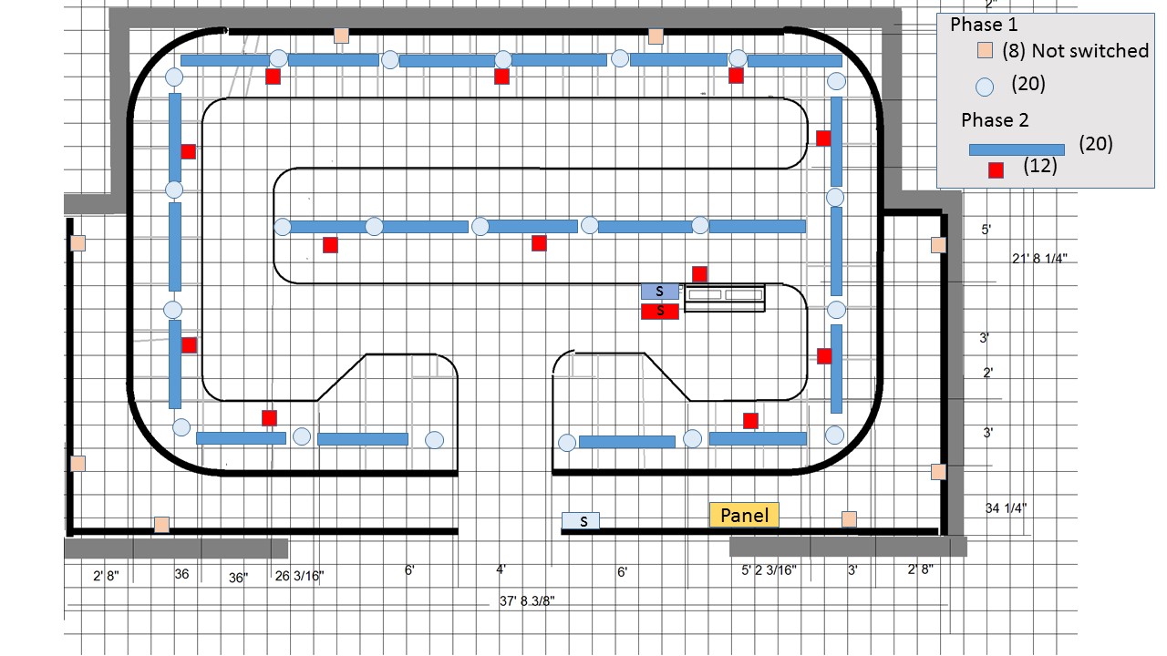 |
Master Electrical and Lighitng Plan showing flourscent light fixtures, HUE light fixtures, out lets and switchng. Phase 2 is to be installed after the bench work is comlete, |
Planning the Lighting of Layout Structures
As part of your planning process, it is a good idea to consider how you will handle the lighting of structures. What type of lights will you use? How they be powered, installed, wired and switched? Do a little research. There are a lot of good way to do this. Just for reference, here is whar I do.
As I mentioned before, I will use 5 mm LEDs for lighting structures of the A&BR2. These will be wired in parallel on the 5 volt switched bus and each will be in series with a 200 ohm resistor. Each will draw about only 12ma, so the 5 amp bus I plan to use is more than ample. There will be two 5 volt power buses on the wire mounting board than run all the way around the layout. Both will take power from the same 5 volt supply: one will be switched for layout structure lighting and one will remain on to supply power to dwarf signals. The switched leg will be switched using TrainController to address a DS64 stationary decoder with the polarity reversing characteristic of the DS64 output converted to a current ON/OFF circuit using a zenor diode. The DS64 output will then operate a relay to turn the switched leg of the 5 volt power bus on or off and thus turn layout lights on and off.
Labels
Developing a comprehensive labeling scheme is a central part of my layout planning process. I suggest that you look at the way I do it, and then create your own scheme. It will be more meaningful and helpful, if you create your own as opposed to trying to figure out mine. I include my scheme just to give you a model and to list all of the areas you need to consider designing labels for.
I create label forms in WORD for bus wires, feeder wires, the wire mounting board, and for all barrier blocks including occupancy sensors, power managers, tortoise interfaces, power supplies and layout lighting distribution blocks and so on. Below is a sample of a Tortoise barrier block label. To the right are labels for the sides of the Tortoise machine. These also serve as labels for the bundle pass-through holes in the bench and in the wire mounting board. In the center is the label for the Tortoise Interface Barrier block, and to the left an under-the-bench label for the entire Tortoise Interface. Notice the label background color-coding. Green is for Power District 90-1, that is, the 16 blocks serviced by BDL 95 and the adjacent routes.
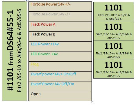 |
Below is a sample of a BDL168 barrier block label. These go on the plastic cover of the block. This one is for BDL168 # 95 monitoring blocks 95-1 through 95-16.
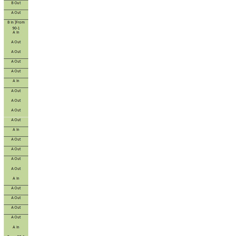 |
Below is a sample of a label sheet for Track Power feeders. This one is for outputs 1-4 on BDL168#95. These are for wire mounting board pass-through holes, for under-bench labeling for the pass-through holes where the feeder bundles will branch off the man bus and for labeling individual dropper pass-through holes.
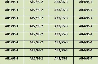 |
Below is a sample of two wire mounting board labels.
|
Here is sample of the label I use for the pass though hole in the wire mounting board for a layout lighting sub-bus.
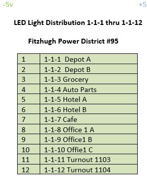 |
Creating labels like this in the planning stage really helps keep things organized when it comes to keeping up with and double-checking block, district, and turnout naming and lists. These labels are also a big help in keeping things straight when it comes time to wire your layout, and of course, they are a great aid down the road when it comes to documenting and servicing your layout wiring.
More Detailed Topographical Planning
Before the beginning of roadbed construction and track laying, it is a good idea to develop a more detailed topographical plan for each section of your model railroad. Working section by section these plans will begin with your final track plan elevations and attempt to establish the contour of the landscape that surrounds the track and a more precise plan for retaining walls, rock outcroppings and cliffs, as well as roads and road-grades, tunnel entrances, and bridges.
Begin with a Xtrack CAD print out of the section to be considered. This should include all track elevations and grade specifications.
Next make any change you want to the raods in your XCAD drawing and lightly pencil in where you want large flat homasote areas, terracing, and streets or roads. Then consider the mountains that will go over open bench work and pencil in a rough topo indicating the location of any retaining walls, tunnel entrances or rock cliffs etc. At this stage, I often find it useful to go on line and use my search engine to locate photos of the kind of topographical features I am trying to design and model. Such photos can bring a lot of new ideas to the table, and they are useful later on as guides for installation and painting
One again, what is created here is a guide for installation. No matter how rough your drawings, this more thought-out version of the plan varies considerably from the rough overall topo we developed earlier in this tutorial. Still even at this stage, it is not intended to be rigid, and as you progress, you will undoubtedly get ideas that vary from the plan as you begin to see your terrain take shape in 3 dimensional space.
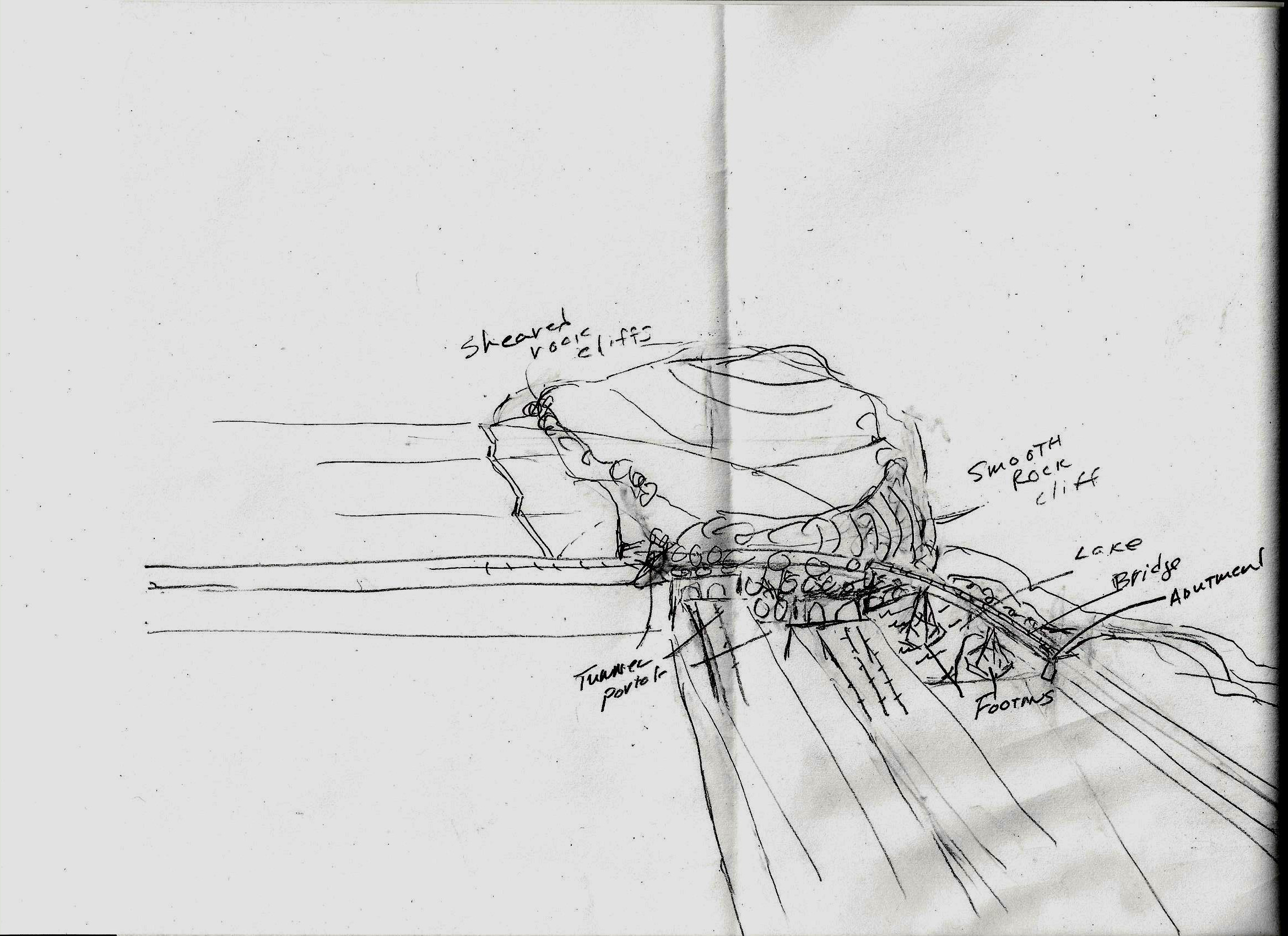 |
Here is a rough sketch of a mountain and a lake from the A&BR2. Here I have roughed in the lower sheared roack clifffs (little circles), the high smooth rock cliff rising form the lake, the lake surface, a curved bridge with abutments and footing locations, 7 tunnel protals, and the generqal shape and height of the mountain. |
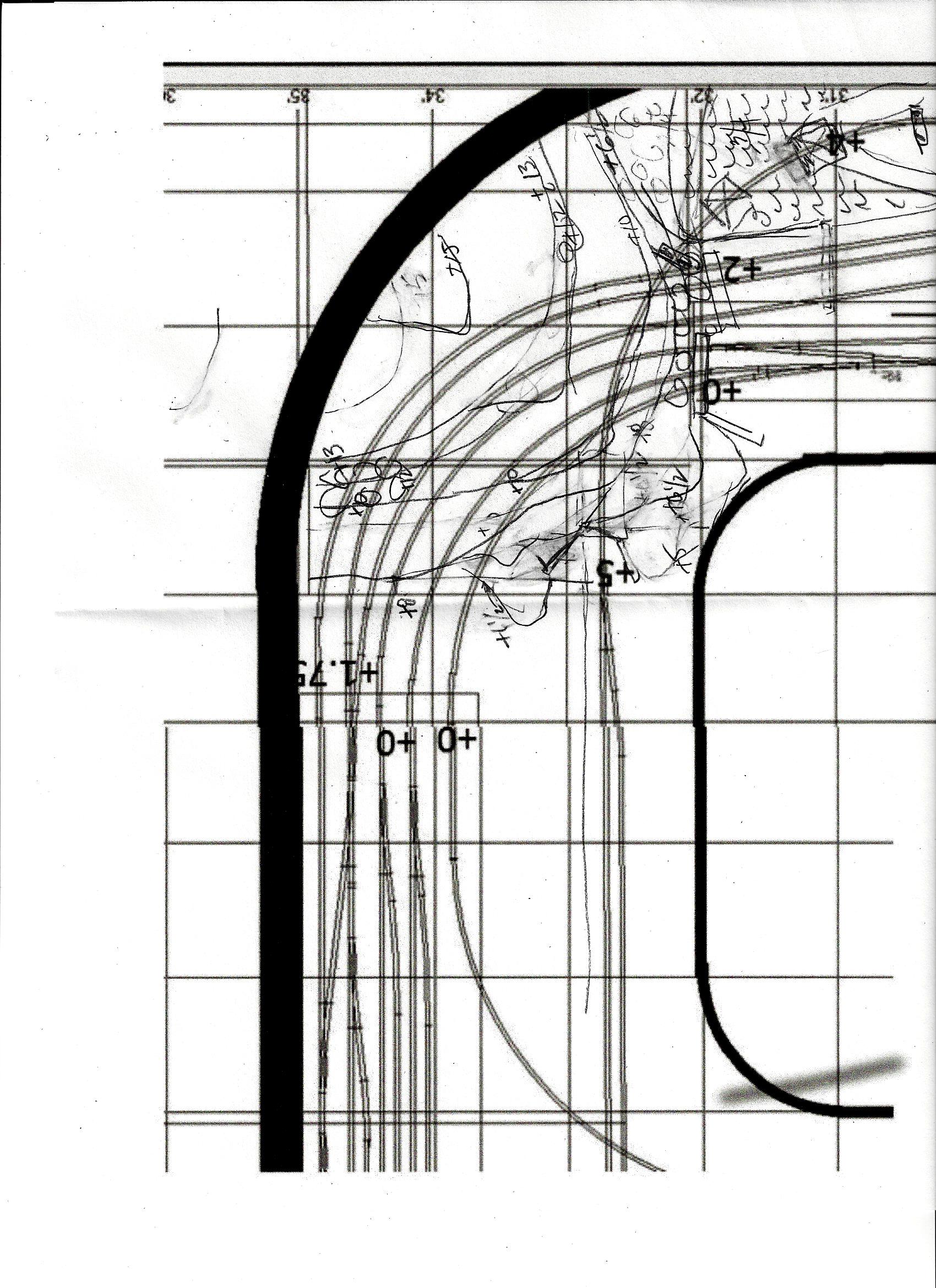 |
Here is a rough topo of the same thing. This supplies a footprint and various elevations, which is useful to ensure that the the elevations of your scenery a various places are in line with your track elevations. |
 |
The high rock cliff noted in the sketches above was inspired by this photo, which I found on line. I will use this image to guide me in shaping and painting my model smooth rock cliffs. |
Conclusion
This tutorial is meant to examine the planning process itself. The specific examples above simply show the way I do it, and there is nothing particularly magical about that. You may create your own documentation, schematics, labels, track plans, sketches etc. using any number of methods. The point is to proceed from the general to the specific, and along the way to incorporate and consider all of the various elements of your model railroad in an interactive way. A good plan should include not just a track plan and a wiring scheme, but also bench work, scenery design, layout lighting, train room lighting, HVAC, signaling, grounding, power supply methods, and more. Such a plan must take into account that a change to any one of these elements can often effect many other elements.
Good planning requires a balance between rigidity and flexibility. The trick is to develop a plan that is complete and rigidly consistent in its naming, labeling, and documentation formats, while at the same time is flexible enough to accommodate changes that may be needed as you begin to implement your plan. Having a good, comprehensive, well-thought-out plan that takes everything into account will save a lot of work and minimize frustrations when you build. It will save time and money, and supply critical documentation that will be invaluable later on when it comes time to repair, service, and preform routine maintenance.